
1. Definition
2. The Internal Structure
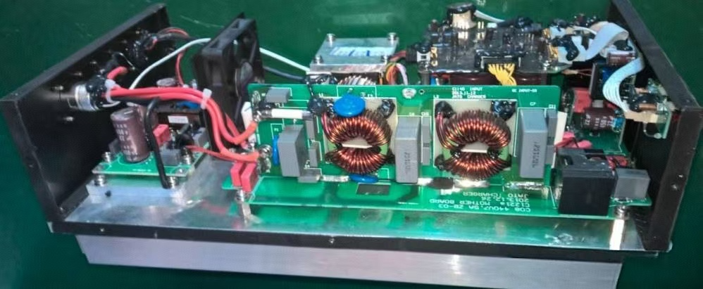
The internal structure of vehicle charger can be divided into 3 parts.
Main circuit, control circuit, wiring harness and standard parts.
3. Conversion Principle.
220Vac filtered by EMI filter circuit, through a ACDC converter rectifier, AC rectified to DC, and then by the PFC power factor calibration circuit for boosting and then sent to the switch and transformer frequency boosting, through the LLC over the second rectifier filtering output highvoltage DC to the power battery charging (the first time 220Vac rectified to 310Vdc, the voltage is not enough to be boosted to convert) two times)
Main Loop:
The main loop circuit is generally divided into two stages:
-
Front Stage: The Power Factor Correction (PFC) module, which improves the input power factor and reduces harmonic distortion. This enhances electricity utilization and minimizes power loss during AC to DC conversion by aligning voltage and current phases.
-
Back Stage: The DC-DC converter, typically an LLC module, which regulates the current and voltage to meet battery charging requirements and provides electrical isolation.
Control Circuit:
The control circuit manages signal reception and charging operations through sensors, the ECU, and the IGBT driver.
Functions:
-
Controls the switching of MOSFETs
-
Communicates with the Battery Management System (BMS)
-
Monitors the charger’s status
-
Handles charging handshake and related control tasks
Wiring Harness and Standard Parts:
These components connect the main circuit and control circuit, securing fixed components and circuit boards.
Charger indicator
AC
Power indicator light, when the AC power is connected, the power indicator light is on
Working
When the charger is connected to the battery and enters the charging state, the charging indicator lights up
Warning
Alarm indicator light, when the charger has internal faults or incorrect operation lights up
4. Vehicle Charger Fault Signals:
The vehicle charger fault information is reported via the CAN bus, allowing diagnosis of specific issues. Common faults include:
-
12V Low Voltage Power Supply Abnormality:
When the charger’s 12V module malfunctions, systems like BMS and instrumentation cannot communicate with the charger due to the absence of a wake-up signal.
Diagnosis: If no relay click sound occurs when AC power is supplied, the 12V power is likely abnormal. Check the charging wake-up fuse and relay in the low-voltage fuse box, and inspect charger terminals for loose or backed-out pins.
-
Battery Voltage Out of Range:
During charging, the BMS may function normally, but the charger must detect the battery voltage before starting. If the voltage is outside the required range, the charger will refuse to operate.
Diagnosis: Common causes include loose or backed-out high-voltage plug pins, blown high-voltage fuses, or battery voltage outside the operating range.
-
Charger and Charging Pile Handshake Failure:
During operation, the charger monitors the handshake signal with the charging pile. If the CC (constant current) switch disconnects, the charger interprets this as the charging gun being unplugged and stops charging to prevent damage and extend the lifespan of the charging terminals.
Share:
mercedes benz s350 Audio System Common Troubleshooting and Repair
Tire Monitor System Light for mercedes benz w211 e280,MercedesBenz Driver Information Service