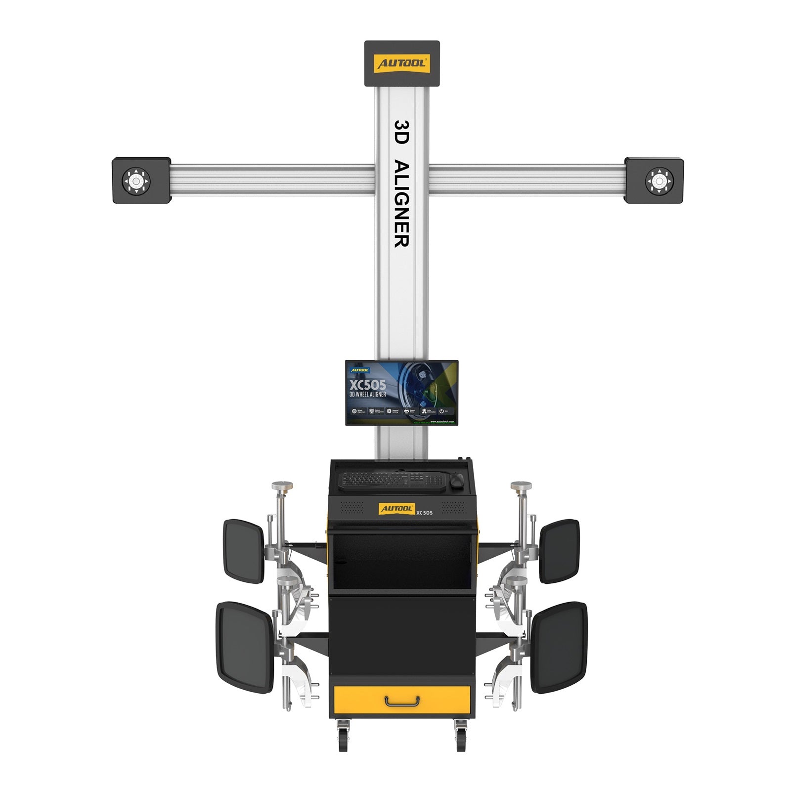


AUTOOL XC505 Wheel Alignment Machine
Popular Combination
In stock! Ships within 1-2 business days.
3-Year Warranty
Complimentary shipping & returns
Pairs well with
AUTOOL XC505 Wheel Alignment Machine
Product Despcription
What is the AUTOOL XC505 Wheel Alignment Machine?
Why Choose XC505 Wheel Alignment Machine
-
High Accuracy Technology: The XC505 uses high accuracy technology to accurately receive data and signals without the need to pull cables, recharge, change batteries or cause signal interruptions.
-
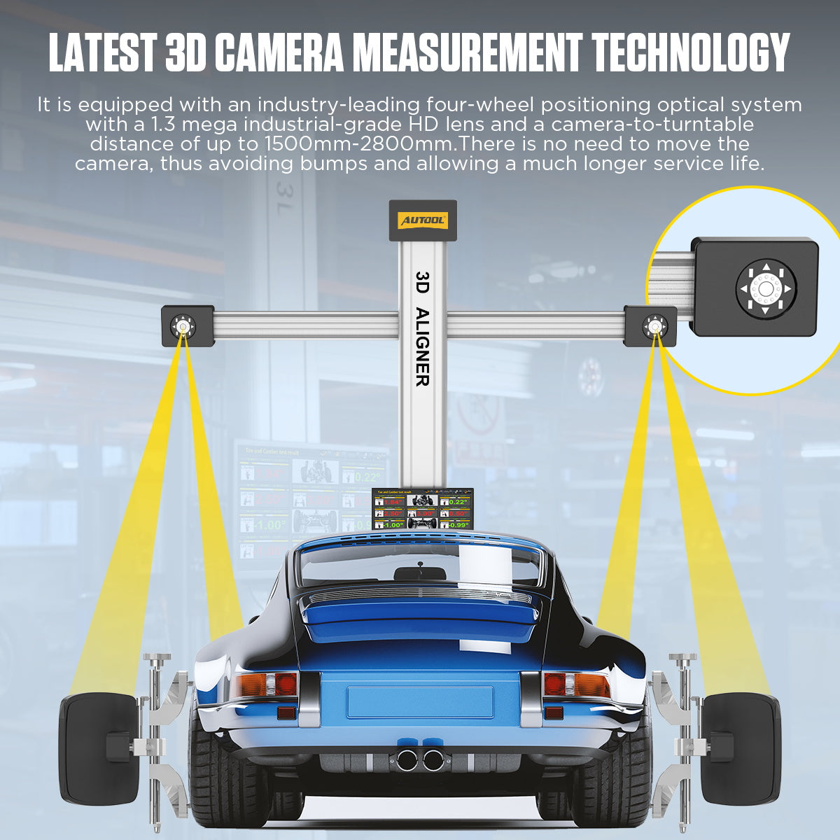
3D Camera Measurement Technology: It is equipped with an industry-leading all-wheel optical positioning system with an industrial-grade 5-megapixel high-definition lens and a camera rotary table distance of up to 1500 mm to 28 mm. There is no need to move the camera, thus avoiding vibrations and ensuring a significantly longer service life.
-
13 Languages: The XC505 supports multiple language settings, including Chinese, English, Spanish, Russian, German, Farsi, Arabic, Lithuanian, Japanese, French, Thai, Portuguese, Korean languages. Unlimited language settings make it easier to use.
-
Full Body Dimension Measurement System: The XC505 has a comprehensive range of measurement parameters, supporting toe-in, camber, steering axis inclination, caster, thrust angle, wheelbase and wheelbase difference, track width and track width difference, diagonal and other data measurements.
-
Global Database: The XC505 has a unique, comprehensive and accurate database for retrieving vehicle chassis data, supporting quick selection of vehicle make, vehicle series and year, vehicle model and year, database settings, and searching by make and model keywords;
How To Use AUTOOL XC505 Wheel Alignment Machine?
-
Step 1: Position the vehicle on the platform, ensuring that the vehicle is aligned straight ahead, with the front wheels at the center of the turntable. After parking the vehicle, straighten the front wheels, turn off the ignition switch, and engage the handbrake. Place the brake blocks at the rear wheels to prevent the vehicle from sliding, then release the handbrake.
-
Step 2: Carefully inspect all chassis components, including bushings, bearings, wishbones, ball joints, shock absorbers, tie rod ends, and steering components for any looseness or wear. Additionally, check the tire pressure, tire specifications, and ensure the tread pattern of both front wheels is identical, with the tread depth of the rear wheels being consistent.
-
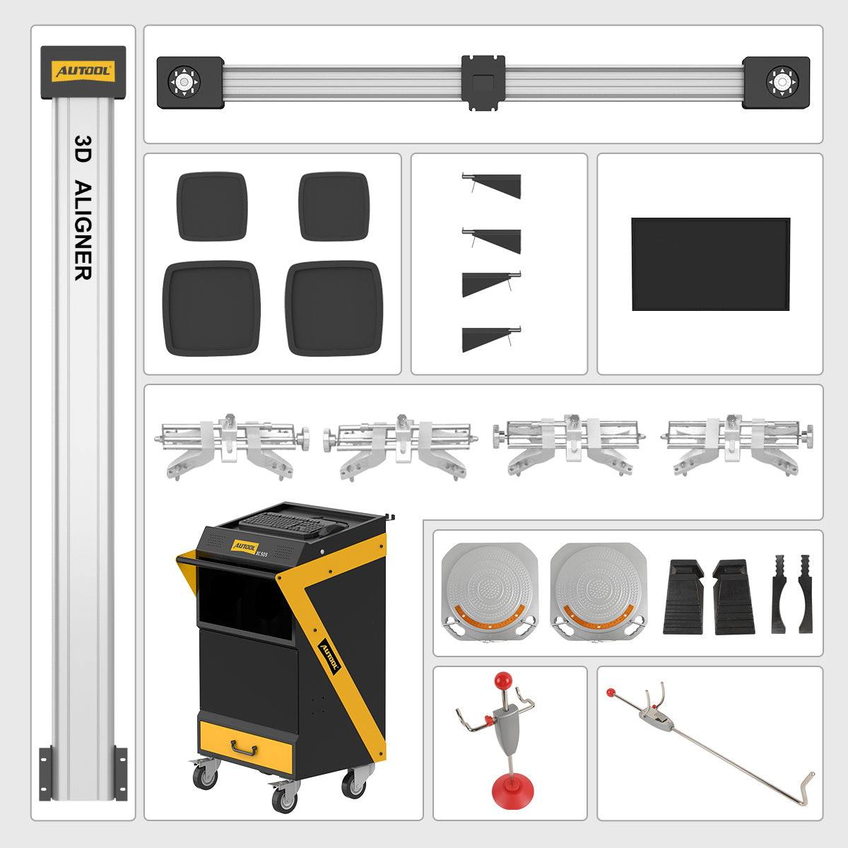
Step 3: Install the four wheel clamps and target plates onto the corresponding tires. Gently tap the clamp to ensure the jaws are securely locked in place, aligning with the outer circumference of the rim. The target plate should be perpendicular to the ground.
-
Step 4: After confirming that all power cables are properly connected, turn on the main power switch of the cabinet. Once the computer starts and the system desktop is displayed, click on the alignment software icon to enter the software.
-
Step 5: Click on the alignment detection option to enter the vehicle selection interface. In the vehicle selection screen, choose the corresponding manufacturer, series, and model of the vehicle, or quickly search for the vehicle data by manufacturer and model. Click "Next" to proceed to the target monitoring screen.
-
Step 6: Once in the target monitoring interface, check whether the target image is displayed properly.
-
The four target images should be centered within the display area, both vertically and horizontally.
-
In the image value display area at the top left of the two images, the brightness values are displayed: the upper reference value should be between 200-240, and the lower value should be between 160-200. If the values are outside this range or too low, click the "Exposure Time Setting" button at the bottom right of the interface to enter the adjustment screen and make corrections.
-
In the image display area at the top left of the two images, the image value should end with the number 21. If it doesn't, check the cleanliness of the target or camera lens.
-
After confirming the above, click "Next" to enter the rolling compensation interface.
-
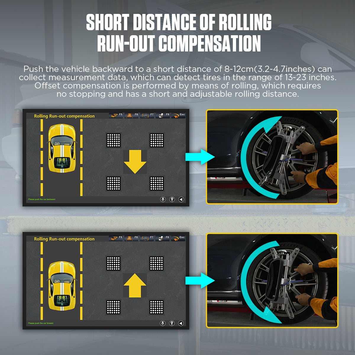
Step 7: Enter the rolling compensation interface and follow the prompts to push the vehicle for data measurement. After pushing the vehicle, the front toe-in and camber data for all four wheels will be displayed. This interface provides real-time data display. If kingpin measurements are not required, you can compare the four-wheel alignment data in this interface to diagnose any issues with the vehicle and make necessary adjustments. (Before making adjustments, remove the turntable and side slip board's locking pins, and use the steering wheel bracket to secure the steering wheel). To test the kingpin, click "Next" to enter the kingpin measurement.
-
Step 8: After entering the kingpin measurement (ensure the turntable locking pins are removed, and use the brake plate fixture to secure the brake), follow the prompts for the kingpin measurement. Once completed, the vehicle measurement data screen will automatically appear. This is a real-time display interface. In this interface, compare the four-wheel alignment data to diagnose any issues with the vehicle and make the required adjustments. (Before making adjustments, remove the turntable and side slip board's locking pins, and use the steering wheel bracket to secure the steering wheel). After adjustments, click "Next" to enter the report printing interface.
-
Step 9: In the report printing interface, enter customer information such as name and license plate number as required, then save the information. If a report is needed, click the "Print" button in this interface to print the report.
-
Step 10: After finishing the work, exit the measurement software system and return to the desktop, then click to shut down. Remove the wheel clamps from the vehicle and place them in the
-
Step 11: Afterward, first turn off the computer host power, and then turn off the main power supply. Drive the vehicle off the platform and clean the area.