Bring Low-Clearance Cars Onto an Alignment Scissor Lift
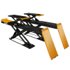
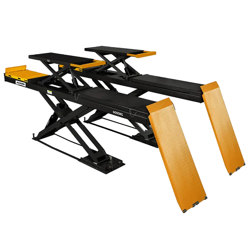
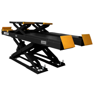
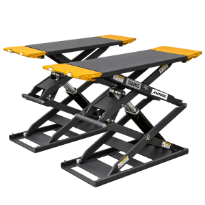
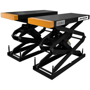
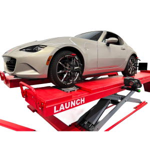
The ATL-4SHU lowers to 190 mm for low-chassis vehicles and combines a main lift with an auxiliary scissor lift for wheel alignment and maintenance work. Six hydraulic cylinders with dual synchronized hydraulics drive both levels. The auxiliary rating is separate and does not add to the main capacity.
- 4,000 kg Main Lift
- 190 mm Lowered Height
- 1,680 mm Lift Height
- Six Hydraulic Cylinders
- Main + Auxiliary Lift
Key Features
-
Ultra-Low Entry
The low lowered height suits low-clearance vehicles and compact workshop layouts.
-
Main and Auxiliary Lifting
The secondary scissor lift raises the vehicle off the main platforms for alignment and service work.
-
Synchronized Hydraulics
Dual hydraulic systems run in sync for smoother lifting and lowering.
-
Extendable Secondary Platform
Single-side extension is standard; a dual-side extendable secondary lift is optional.
-
Layered Safety
Triple mechanical safety devices that unlock automatically during descent, wave pressure locks, a pneumatic mechanical safety lock on the solid-core steel X-frame, and a 24 V safety control circuit.
-
Optional Descent Protection
Infrared level detection and a foot protection device are available as options.
-
Workshop-Grade Build
Laser-cut alloy steel X-frame, shot-blasted and spray-coated surfaces, wear-resistant bearings at the pivot points, and Japanese seals with Italian ball valves.
More Specifications
| Primary platform length | 4520 mm |
|---|---|
| Auxiliary platform length | 1540–1750 mm |
| Auxiliary platform width | 600 mm |
| Load testing | 150% static and 115% dynamic test, per EU testing standards |
How to Use
- Qualify the siteConfirm the installation drawing, concrete strength and thickness, anchors, clearances, power, air supply and approach space.
- Inspect before useCheck anchors, platforms, hoses, cylinders, locks and synchronization components before loading a vehicle.
- Position the vehicleCenter the vehicle and keep doors, tires and bodywork clear of moving parts.
- Set the pickup pointsUse the vehicle manufacturer’s approved lift points and match platform and extension placement to the wheelbase.
- Raise and checkLift just enough to take the load, verify contact points and balance, then continue while watching both sides.
- Engage the locksLower onto the mechanical locks and confirm both sides are engaged before anyone works below.
- Clear and lowerRemove tools and people, release the locks as designed and lower through the controlled descent.
Good to Know
Caution
- Install and anchor only to the specified concrete foundation and layout; obtain the installation drawing before site work.
- Do not exceed the rated load; capacity alone does not prove fit for a particular vehicle or load distribution.
- Stop use if hoses, cylinders, seals, anchors or synchronization show damage, leakage or abnormal movement.
- Infrared, foot or other optional protection is present only when included in the ordered configuration.
- Confirm the voltage configuration and local electrical requirements before installation.

 English
  German
  Spanish