


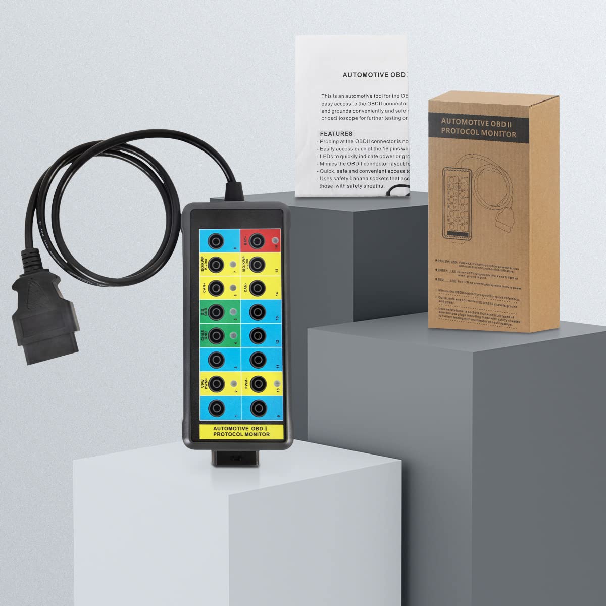
See Power, Ground and Bus Activity at the OBD2 Port
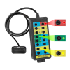
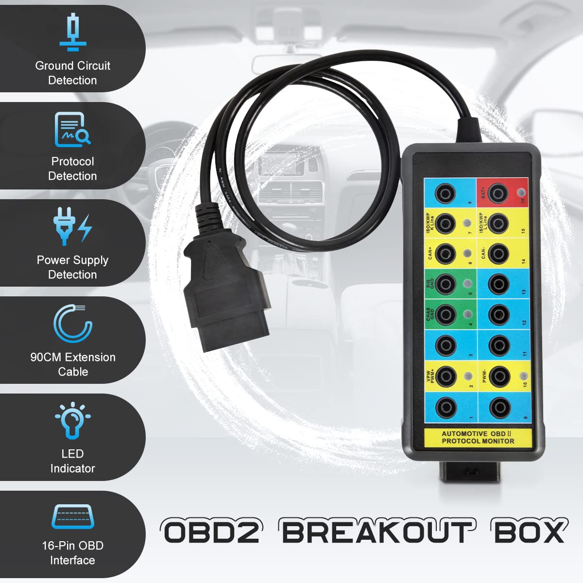
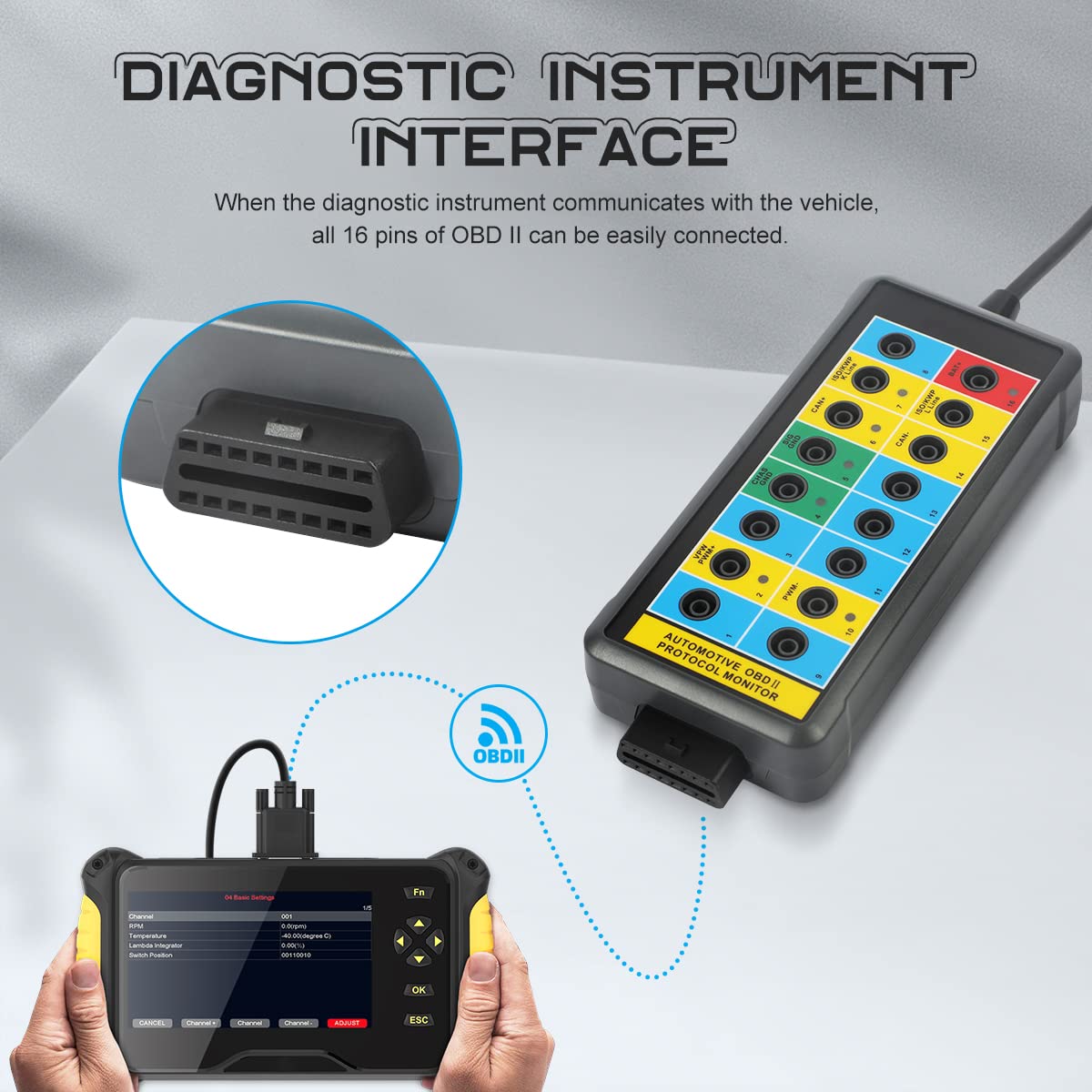
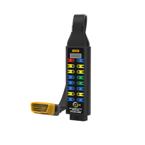
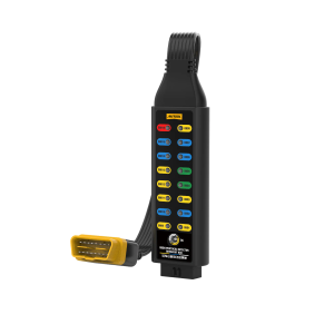
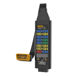
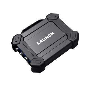
Plugs in between the vehicle’s 16-pin OBD2 port and a scan tool. LEDs confirm power, ground and protocol activity, and every pin is broken out to a banana jack for a multimeter or oscilloscope.
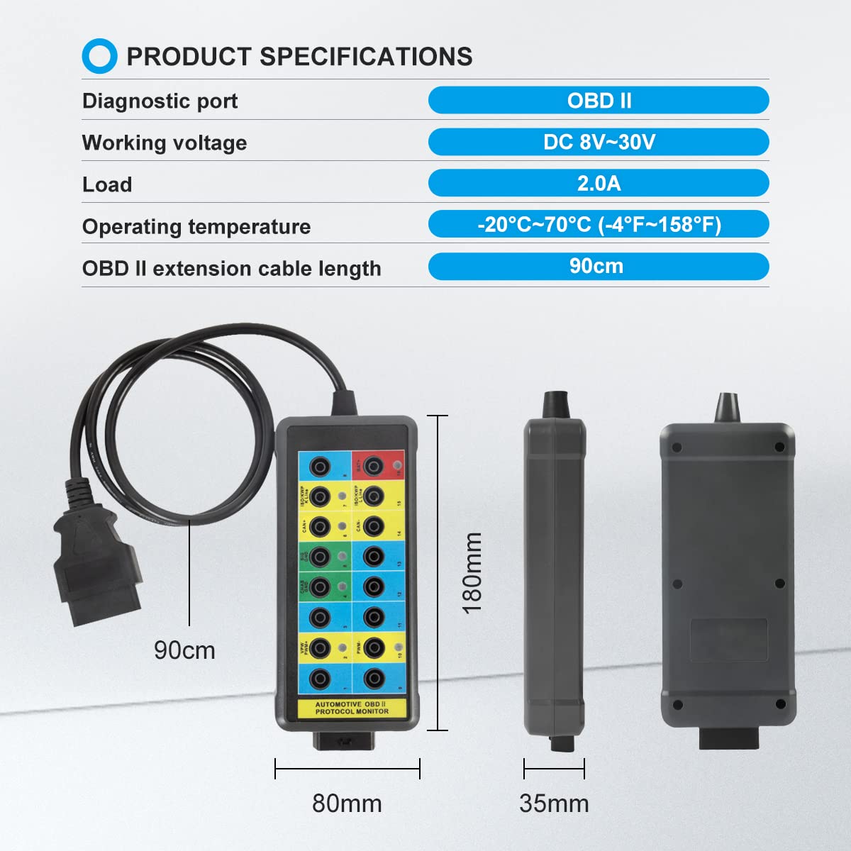
- 8–30V DC
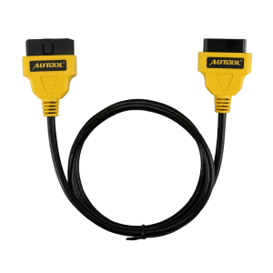
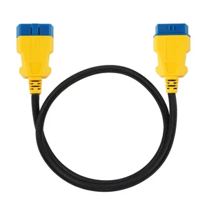
- 90 cm Extension Cable
- 4 mm Banana Jacks
- 3-Color LEDs
Hauptmerkmale
-
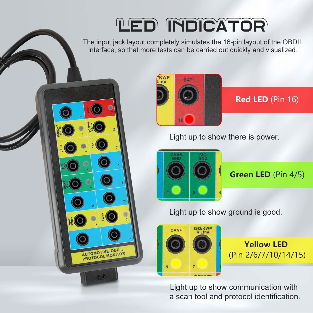
Power and Ground LEDs
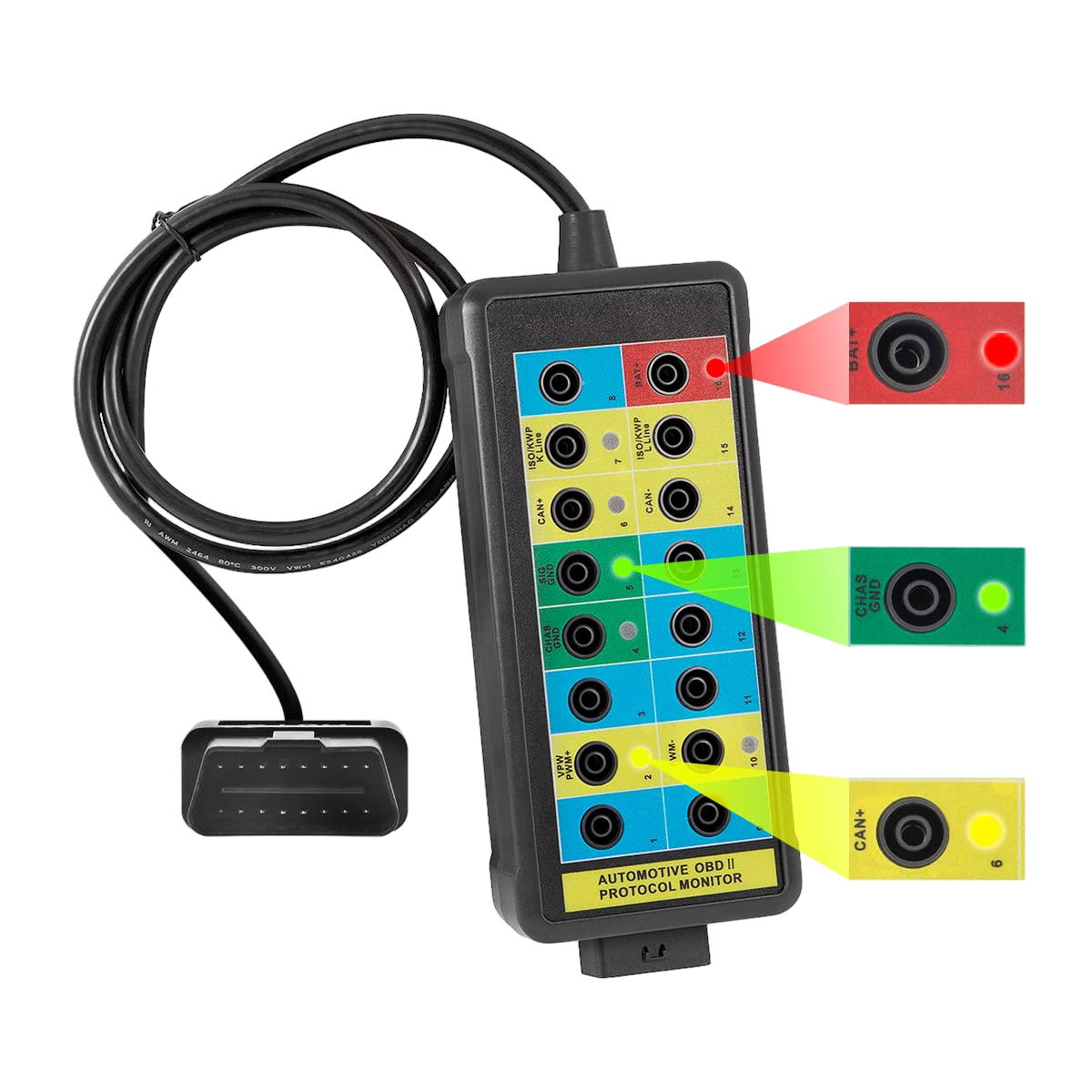
Red lights when pin 16 has battery power; green lights when pins 4 and 5 are grounded.
-
Protocol Activity LEDs
Yellow LEDs on pins 2, 6, 7, 10, 14 and 15 show which lines are active while a scan tool talks to the vehicle.
-
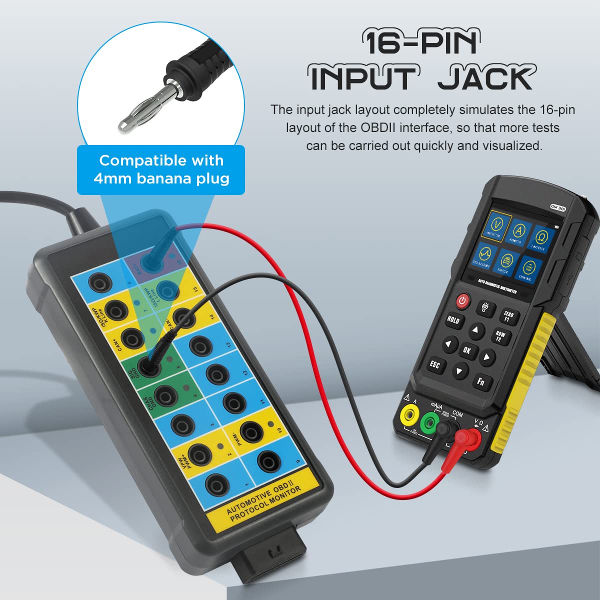
All 16 Pins Broken Out
The jack layout matches the OBD2 connector, so each pin can be probed while the scan tool stays connected.
-
Meter and Scope Ready
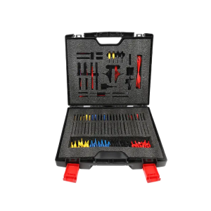
Standard 4 mm banana sockets take plain or sheathed safety plugs.
-
Flexible Lead
The extension cable has an elastic TPU jacket.
More Specifications
| Operating temperature | -20 to 70°C (-4 to 158°F) |
|---|---|
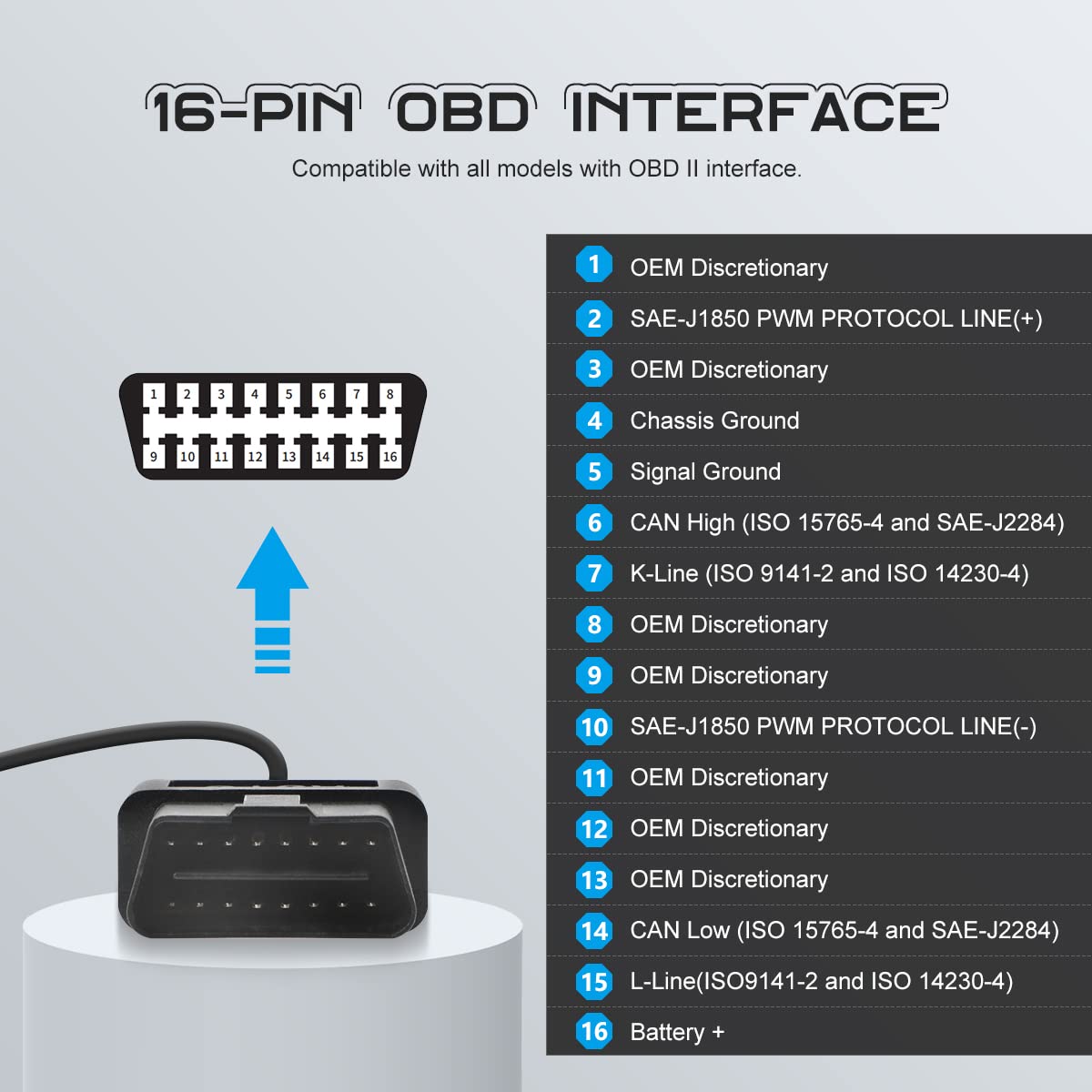
| Pin 2 / Pin 10 | SAE J1850 PWM bus (+) / (−) |
| Pin 4 / Pin 5 | Chassis ground / signal ground |
| Pin 6 / Pin 14 | CAN High / CAN Low (ISO 15765-4, SAE J2284) |
| Pin 7 / Pin 15 | K-line / L-line (ISO 9141-2, ISO 14230-4) |
| Pin 16 | Battery positive |
| Pins 1, 3, 8, 9, 11, 12, 13 | OEM discretionary |
What’s in the Box
- OBD2 breakout box
- Bedienungsanleitung
Good to Know
Caution
- Do not connect any load drawing more than 1 A through the box.
- Never short pins 16, 4 and 5 together, and do not jumper the jacks unless you know the circuit; misuse can damage the vehicle’s data network.













 English
  German
  Spanish