

Trace Power, Ground and Shorts From the Battery Out
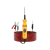
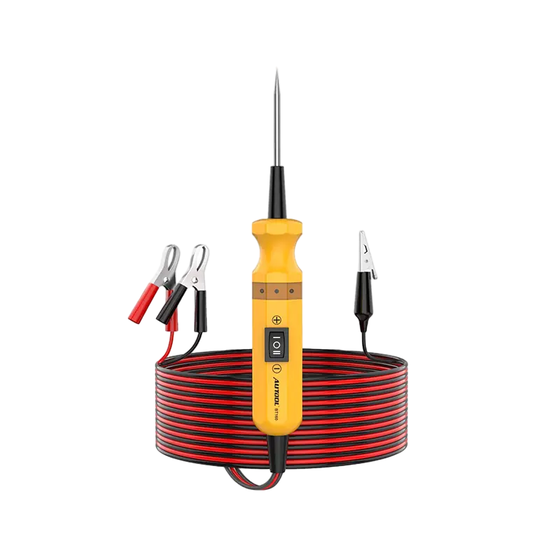
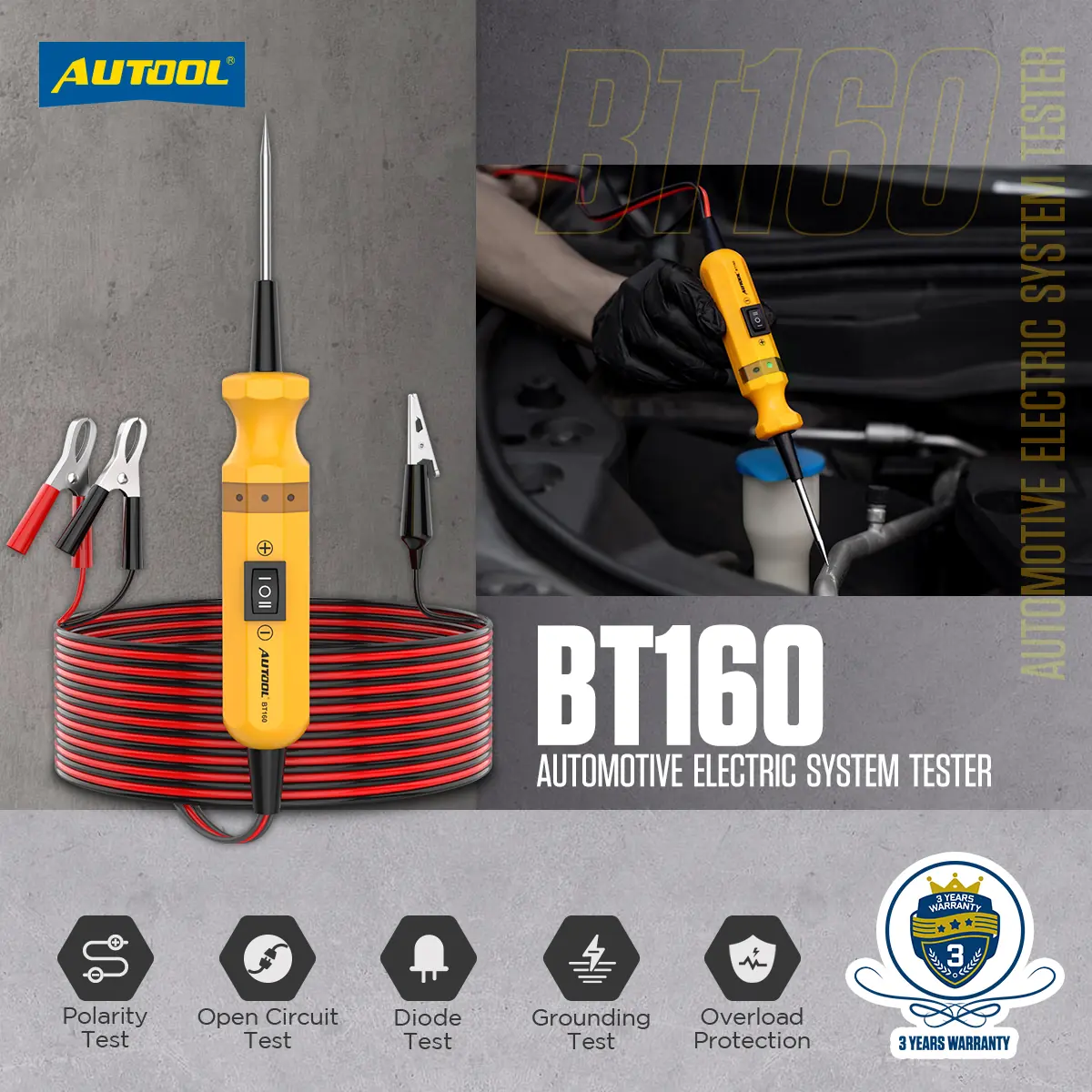
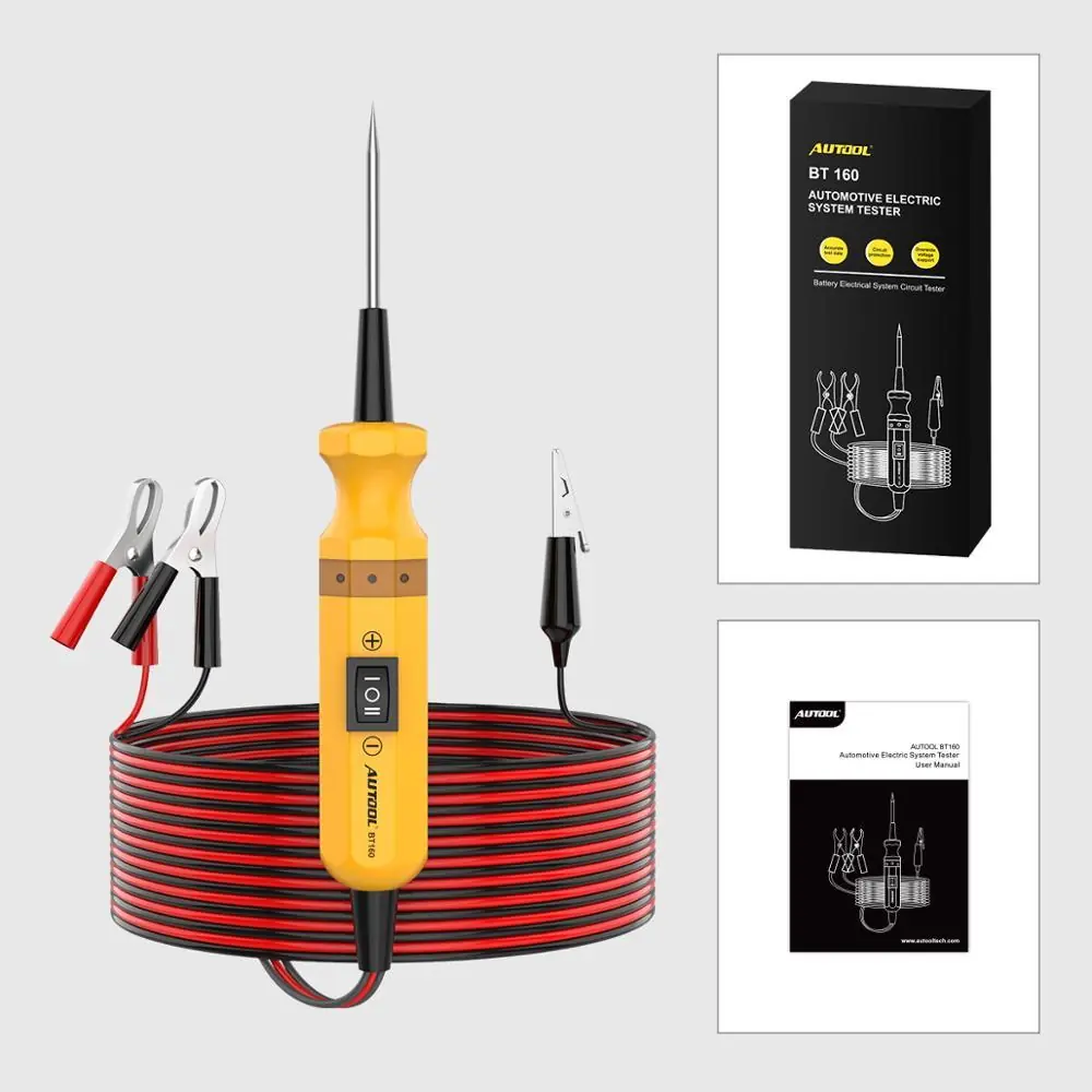
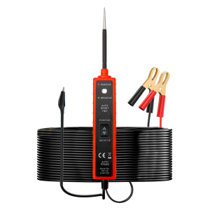
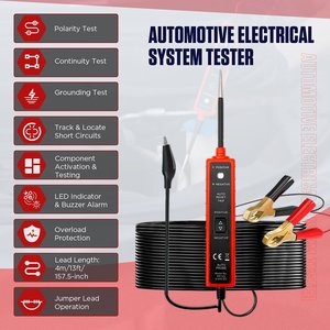
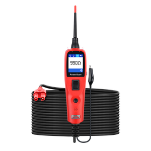
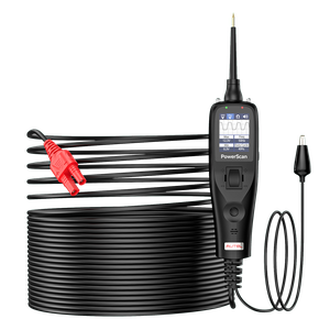
The BT160 is a powered circuit probe for 6–24 V DC vehicle systems: it shows polarity and continuity by LED and buzzer, checks grounds and diodes, and can feed power or ground to a selected component. It has no screen and does not read exact voltage values.
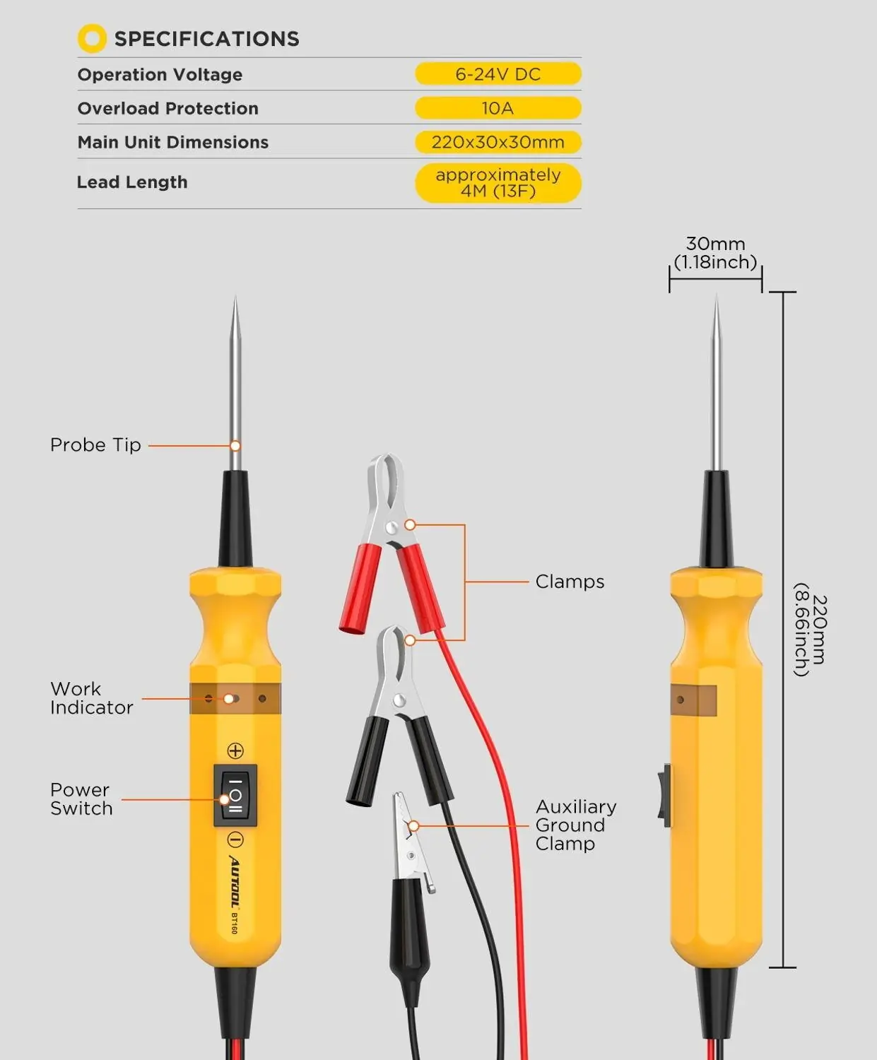
- 6–24 V DC
- 4 m Integrated Lead
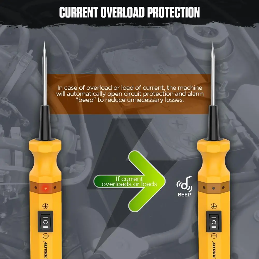
- 10 A Overload Cutoff
- Red / Green LED + Buzzer
Hauptmerkmale
-
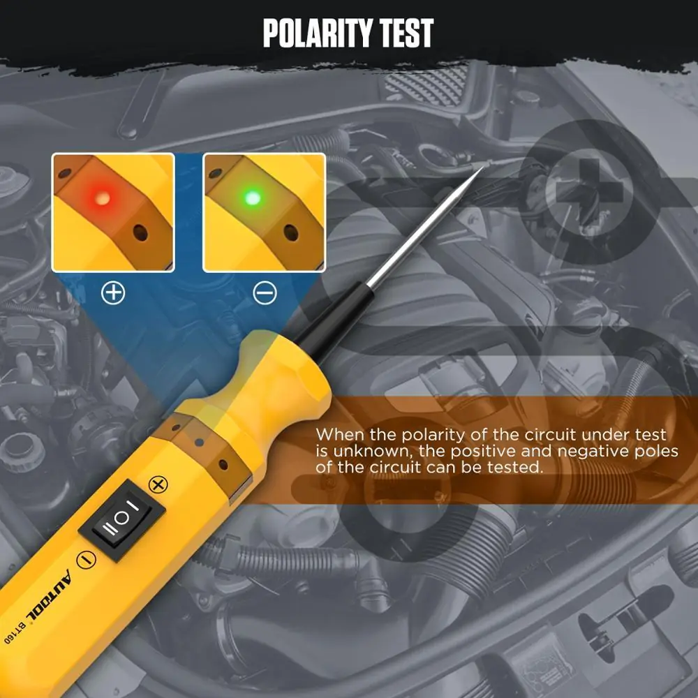
Polarity Test
Touch an unknown contact: red LED for positive, green LED for negative.
-
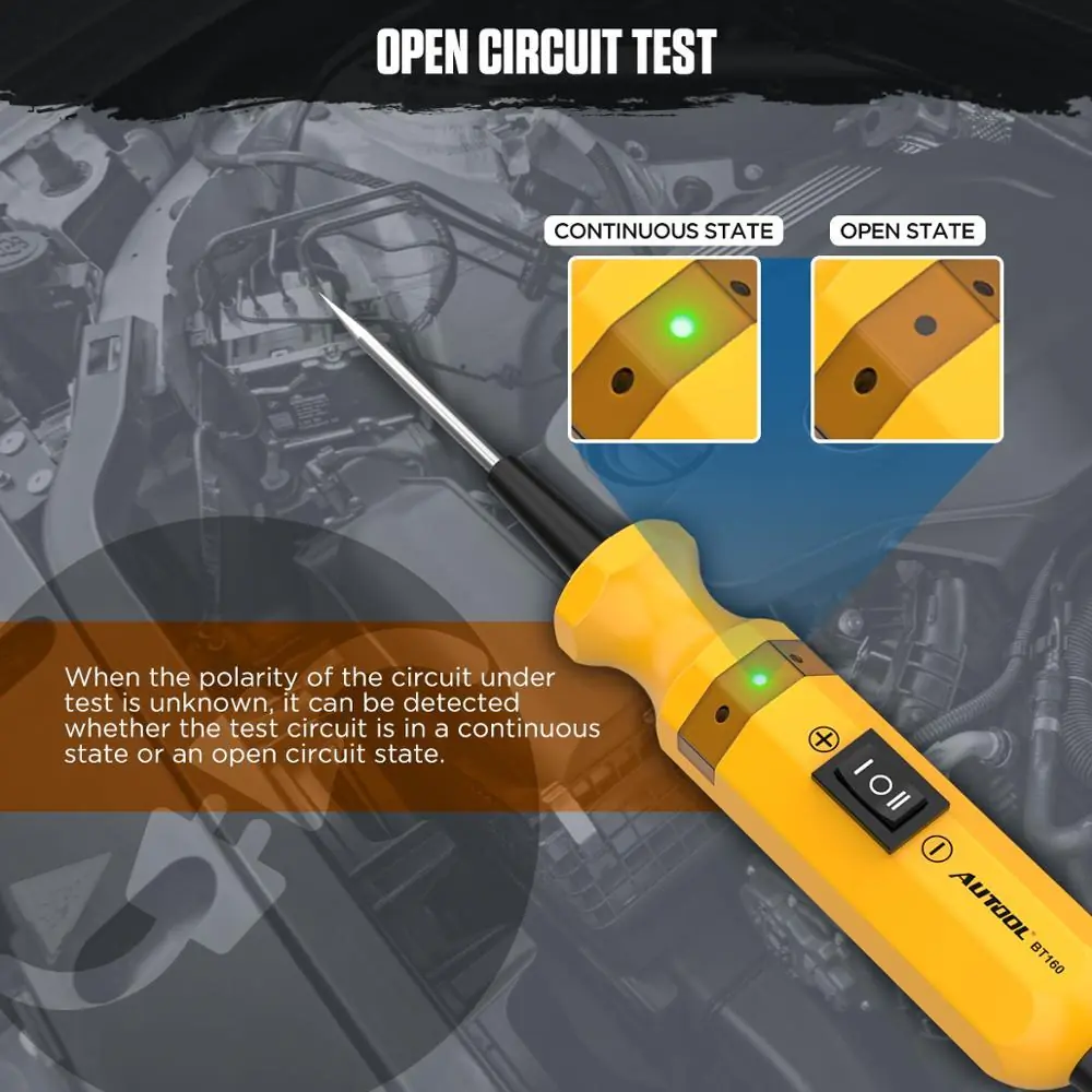
Continuity and Open Circuit
With the auxiliary ground lead on one end and the probe on the other, check wires, fuses, relays and switches for an open path.
-
Diode and Ground Checks
Test a diode assembly, or confirm a component’s negative ground with green LED and buzzer feedback.
-
Short-Circuit Tracing
Remove the blown fuse, start at the fuse socket and follow the harness section by section to find the shorted side.
-
Component Activation
The rocker switch applies positive or negative output to a component on the vehicle or on the bench.
-
Long Jumper Lead
The black clip and auxiliary ground lead are linked through the unit, so it can serve as a long jumper test lead for front-to-rear harness work.
Model Comparison
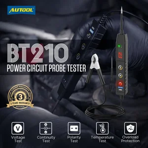
| BT160 | BT210 | BT250 | BT280 | |
|---|---|---|---|---|
| Operating voltage | 6–24 V | 9–30 V | 9–30 V | 9–30 V |
| AC / DC voltage reading | No | 9–30 V | 0–65 V | 0.1–100 V |
| Resistance | No | No | 0–200 kΩ | 1–200 kΩ |
| Power cable | 4 m | 1.1 m | 1.5 m | 6 m |
| Temperature test / LED light | No / No | Yes / Yes | No / Yes | No / Yes |
| Oscilloscope and multimeter | No | No | No | Yes |
What’s in the Box
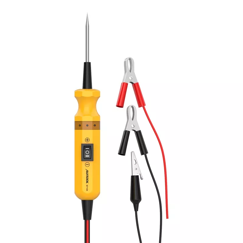
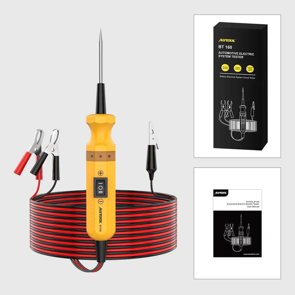
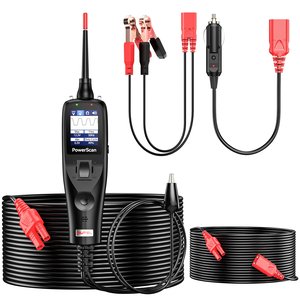
- BT160 main unit with integrated 4 m lead and red/black battery clips
- Auxiliary ground clamp
- Bedienungsanleitung
Anwendung
- Connect to the batteryUnroll the lead; red clip to battery positive, black clip to negative.
- Self-testPress the switch and confirm the LEDs: red for positive, green for negative.
- Probe the circuitTouch the tip to the contact, wire, fuse, relay, diode or terminal for the test you are running.
- Read the feedbackUse LED color and buzzer to identify positive, negative, open, continuous, grounded or overloaded conditions.
- Activate only when appropriatePress “-” for positive output or “=” for negative output; stop at once if the LED changes color with a beep.
Full procedures: BT160 user manual (PDF)
Good to Know
Caution
- For 6–24 V DC vehicle systems only. Not for 110 V / 220 V AC household current or any system above 24 V DC.
- Do not inject power or ground into an ECU, SRS, sensor or data line unless a specific procedure allows it; the tester’s protection does not make those circuits safe.
- Sparks can occur at the probe tip. Do not use near combustible gas, dust or explosive atmospheres.
- If overload protection trips, stop and check the circuit, the component and its rated current before continuing.
Care
- Inspect the case, tip, clips and leads before use; do not use with cracks or exposed wire.
- The probe tip is sharp; store it carefully and away from children.
- Do not disassemble the tester; repairs go to authorized service.

 English
  German
  Spanish