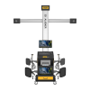
3D Alignment That Follows the Lift and Prints the Report in the Bay
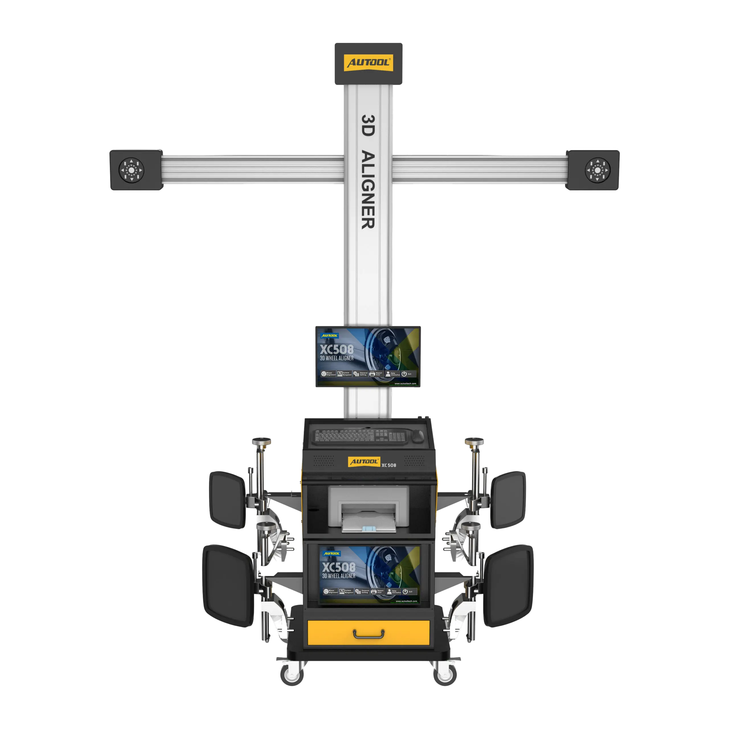
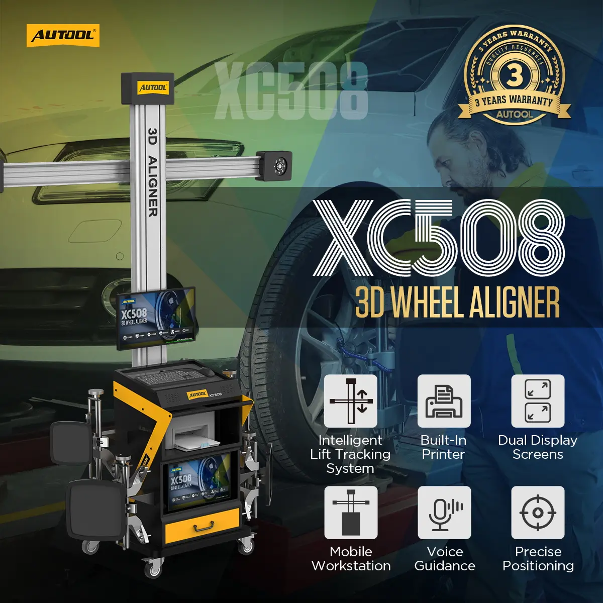
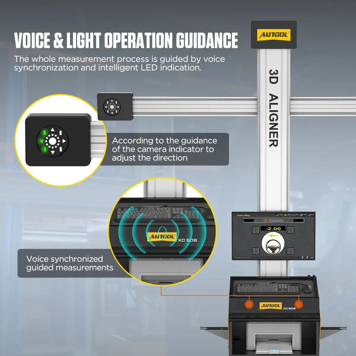
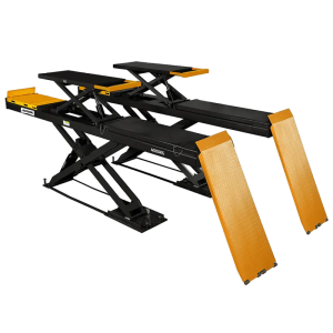
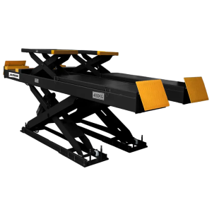
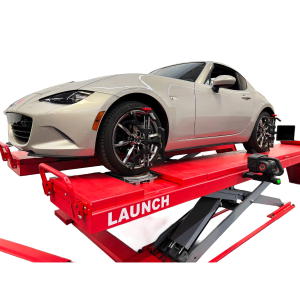
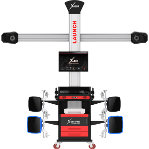
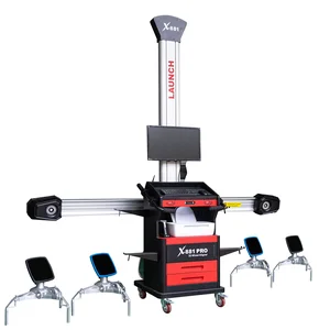
The XC508 camera beam rises and falls with the lift to keep the wheel targets in view, so you can measure and adjust at working height without repositioning the cameras. Dual displays, voice and LED prompts guide the job, and the built-in printer delivers the before-and-after report. A qualified lift and alignment bay are required.
- 5 MP 3D Cameras
- Auto Lift-Height Tracking
- Dual Displays
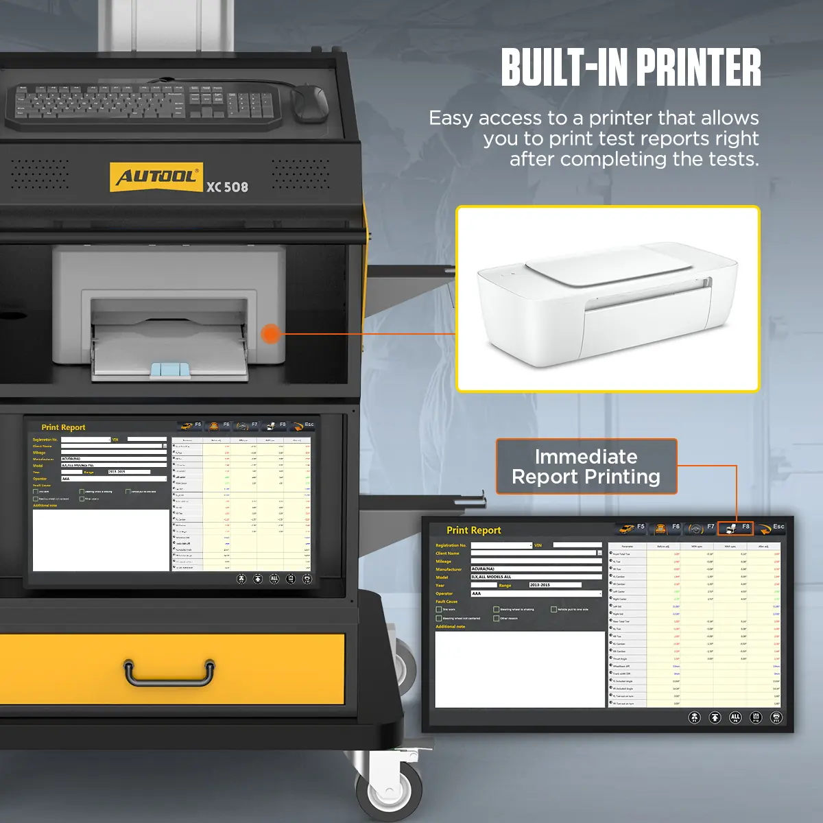
- Built-In Printer
- Toe/Camber ±0.01°
Hauptmerkmale
-
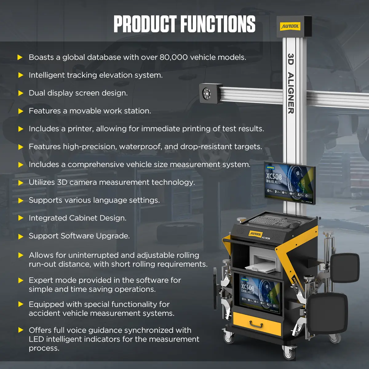
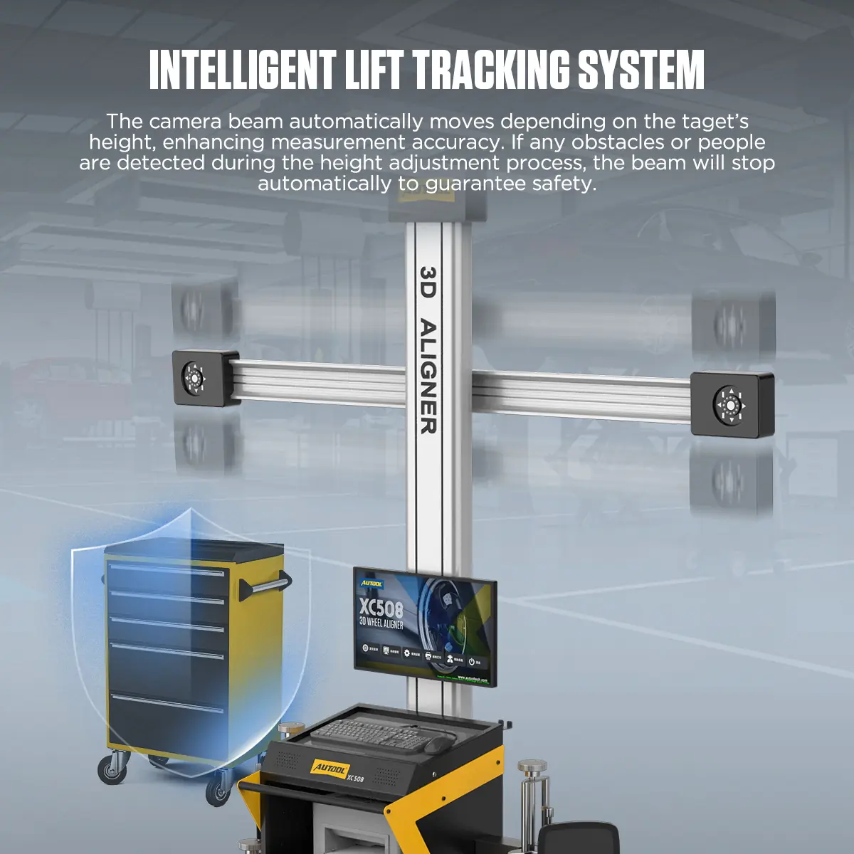
Automatic Camera-Height Tracking
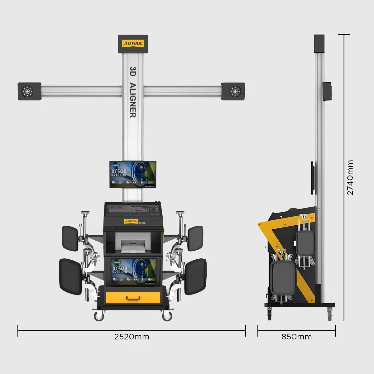
The crossbeam follows lift-height changes and stops if an obstacle or person is detected while moving.
-
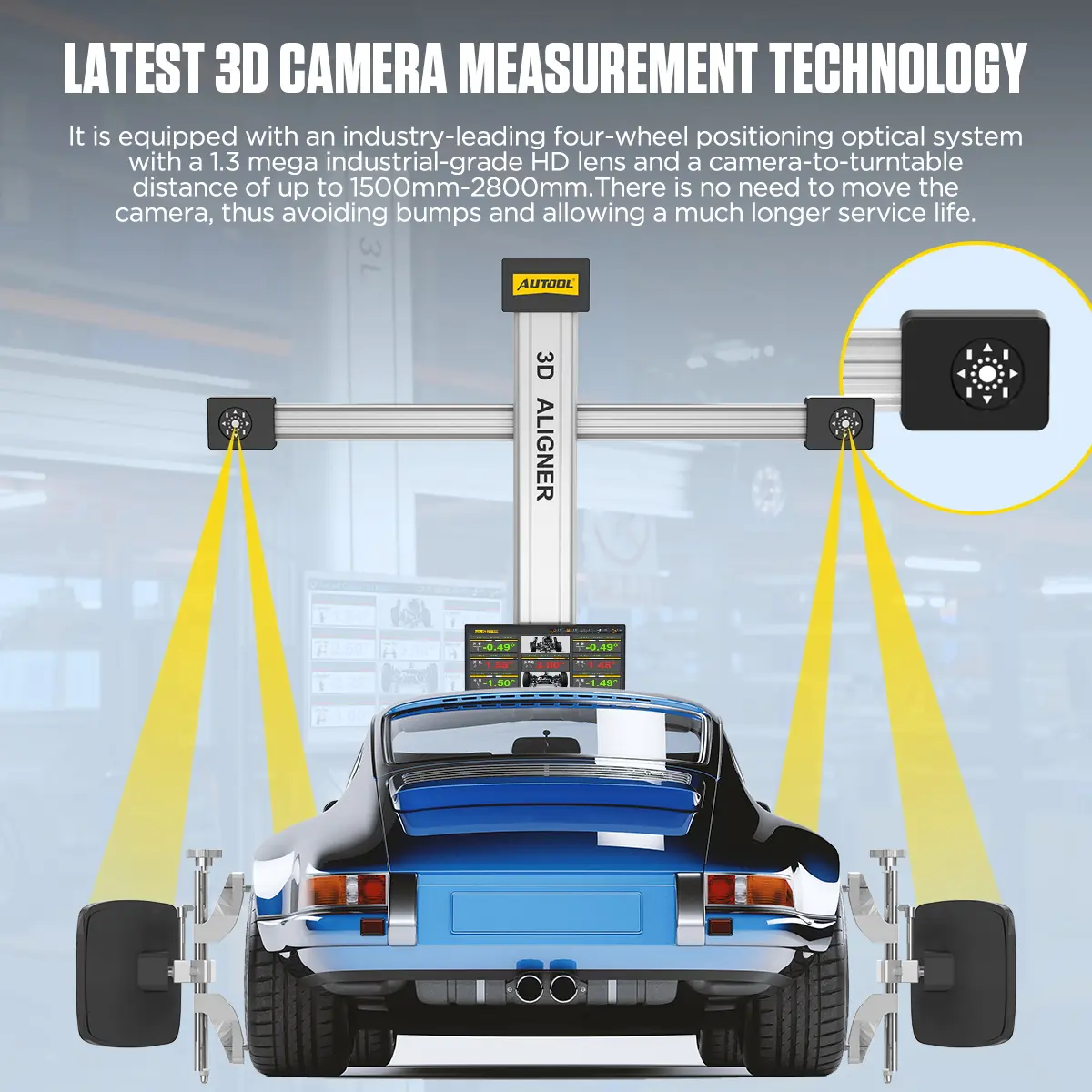
Fixed-Position 3D Cameras
With a 1500–2800 mm camera-to-turntable range, the cameras do not need to be moved during a job.
-
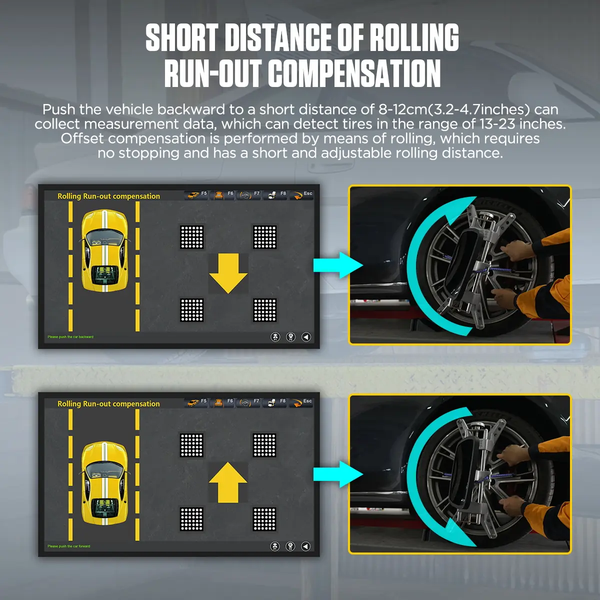
Short Rolling Compensation
Push the vehicle 8–12 cm (3.2–4.7 in) to complete runout compensation.
-
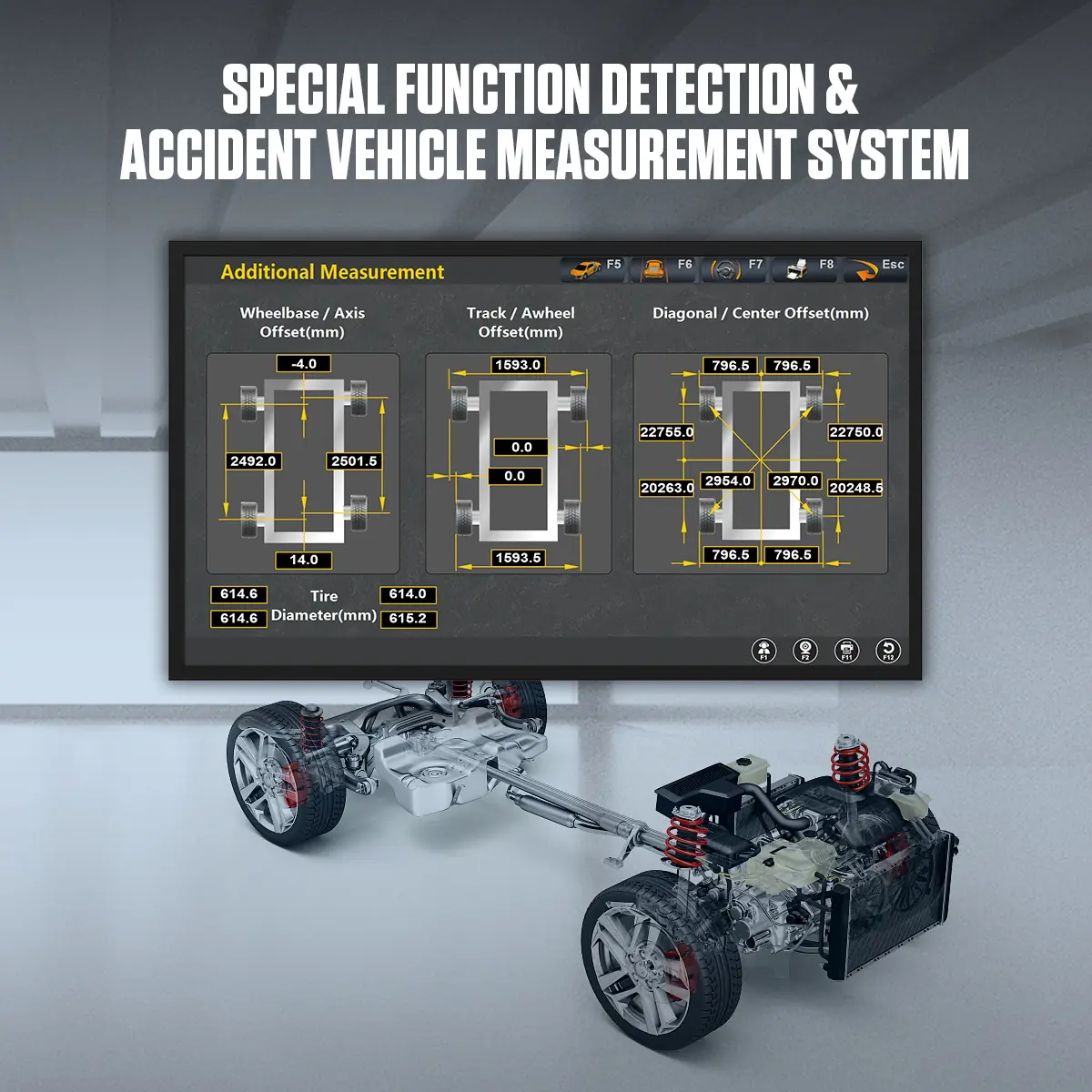
Wheel and Body Geometry
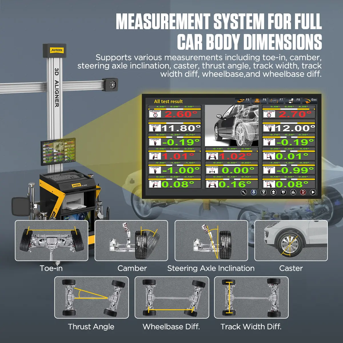
Toe, camber, caster, thrust angle, track and wheelbase with their left-right differences, plus diagonal body measurements for accident vehicles.
-
Large Vehicle Database
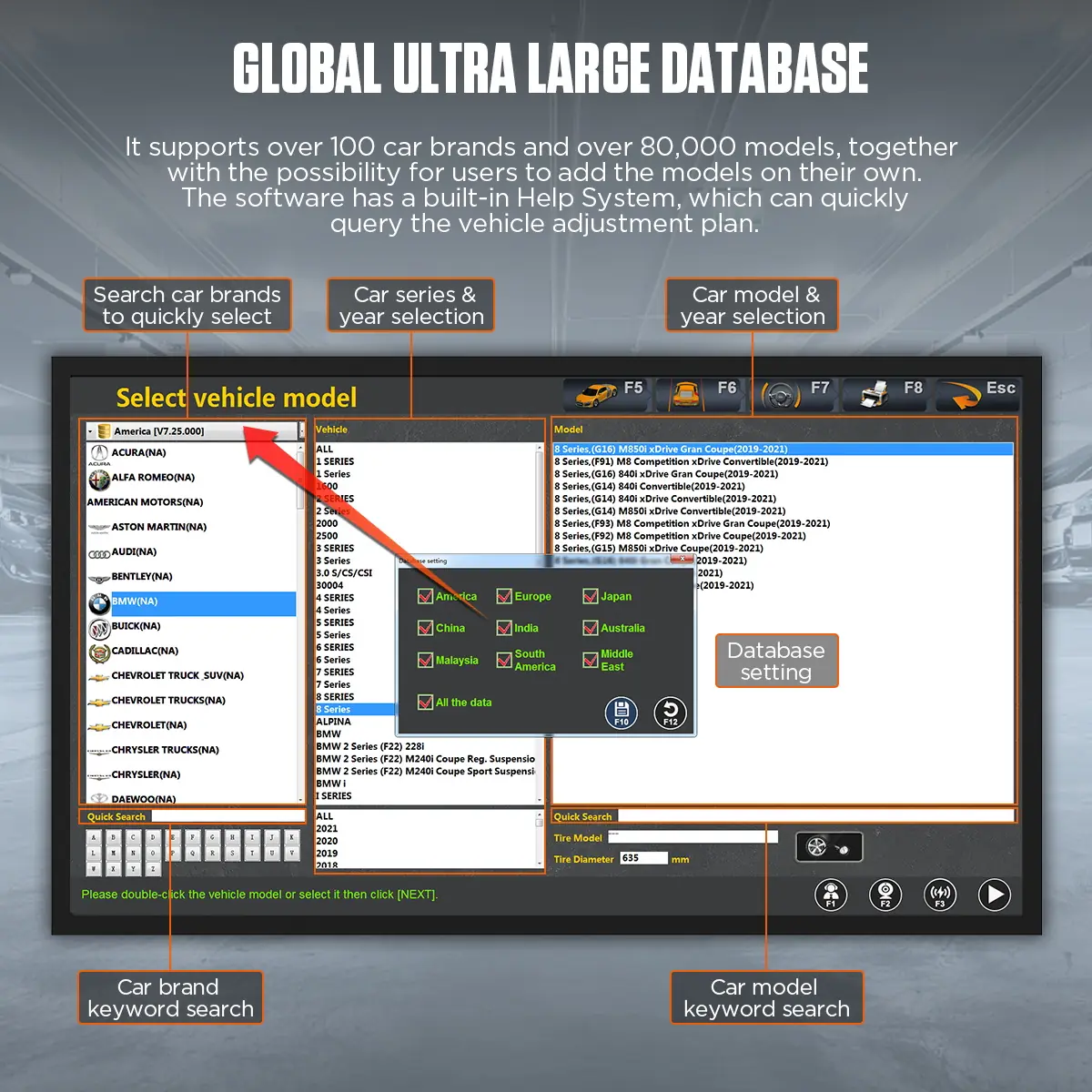
100+ brands and 50,000+ models, with custom models and a built-in help system for adjustment lookup.
-
Guided Workflow
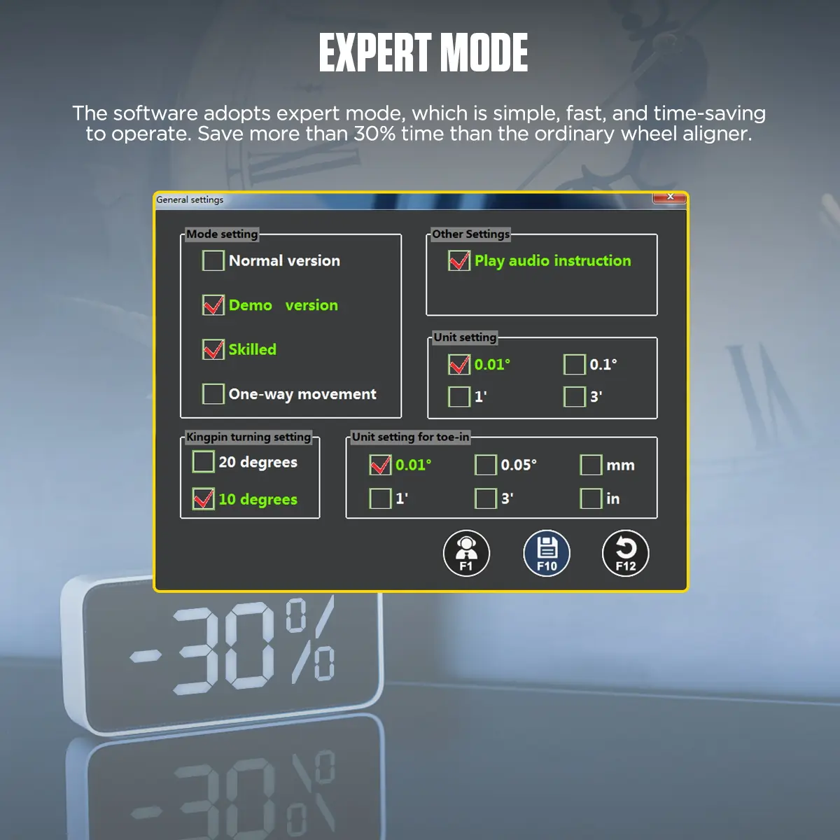
Synchronized voice prompts, LED indicators and an expert mode for faster routine jobs.
-
Mobile Workstation
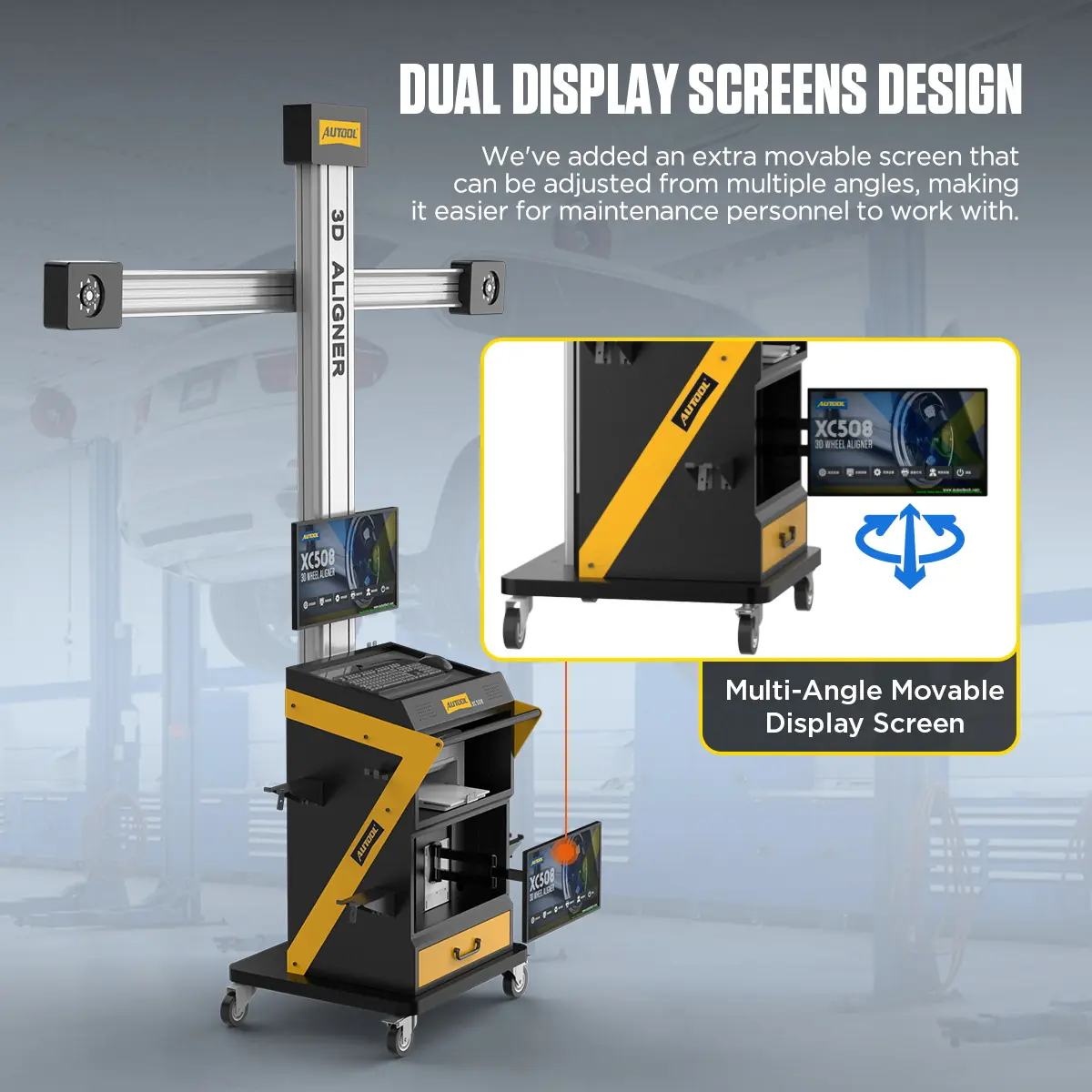
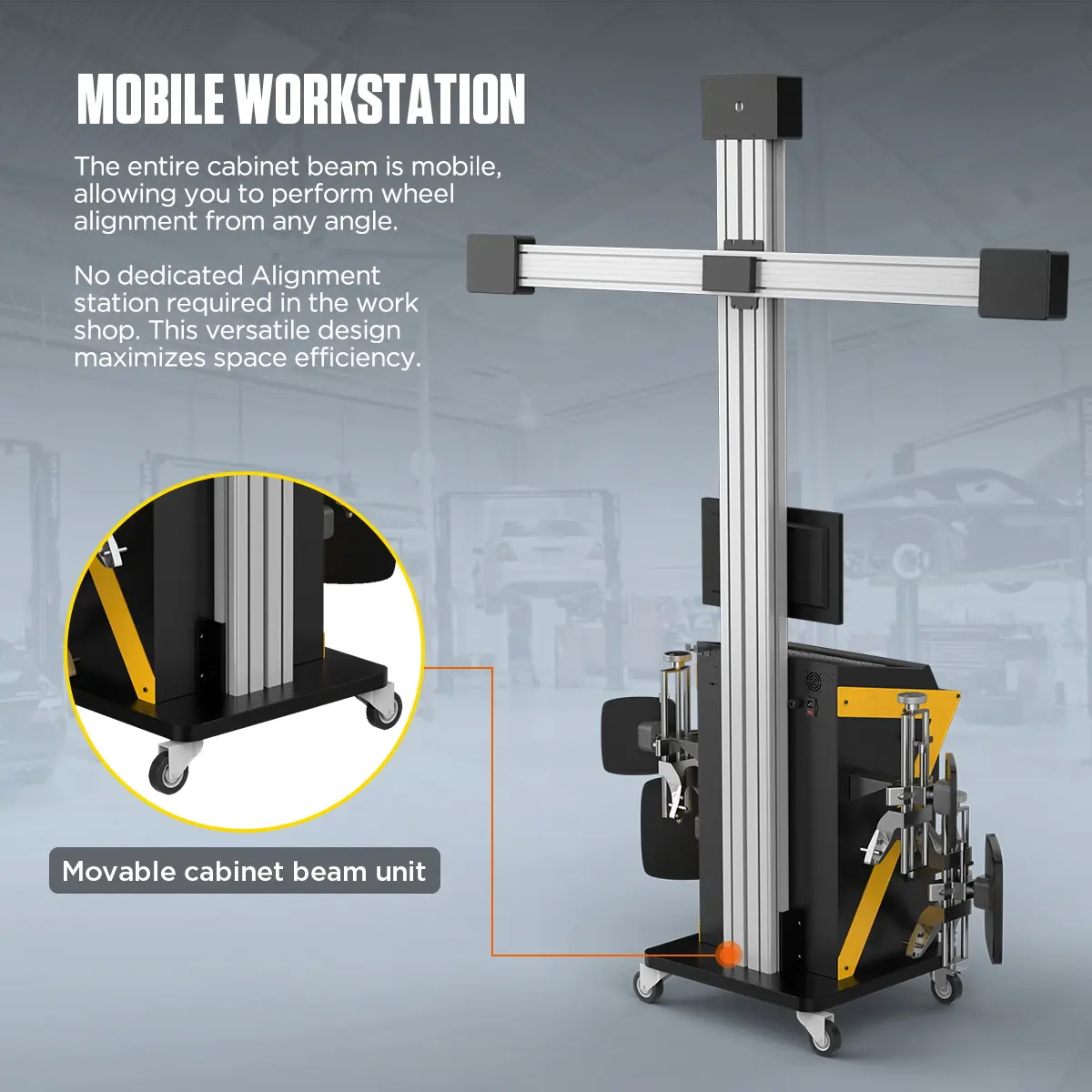
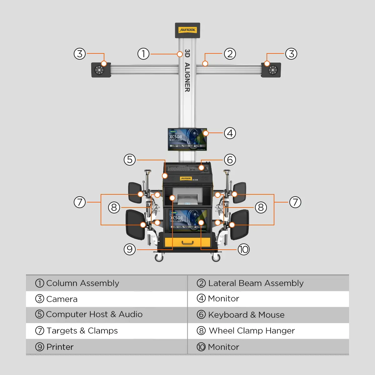
A wheeled cabinet with computer, keyboard, printer and drawer, and an adjustable-angle second screen.
More Specifications
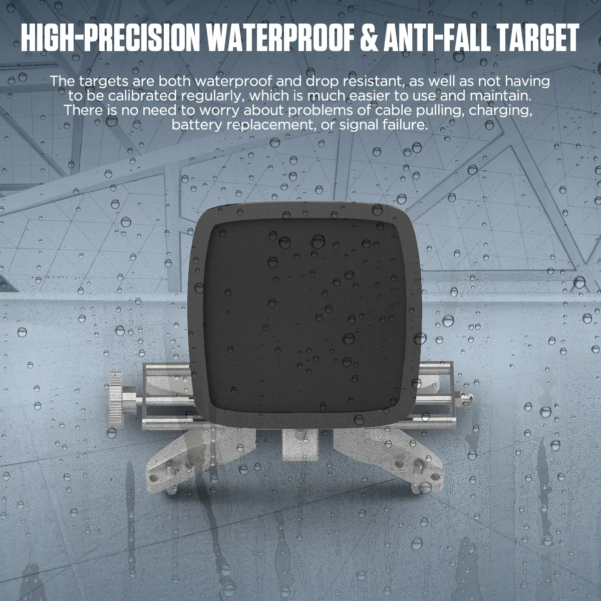
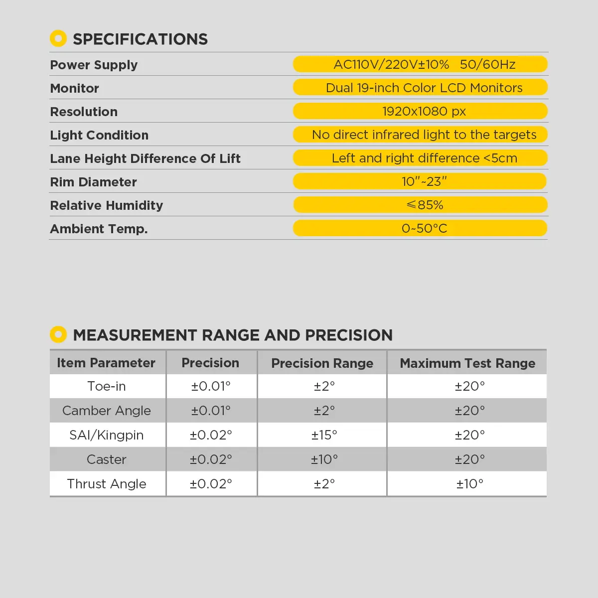
| Targets | Passive, waterproof and drop-resistant; no cables, charging or batteries; no regular calibration |
|---|---|
| Factory calibration | Calibrated before shipping; install and use per the setup guidance |
| Lift platform height difference | < 5 mm |
| Lighting condition | No strong infrared light directly on targets or cameras |
Model Comparison
| XC503 | XC505 | XC508 | |
|---|---|---|---|
| Camera mount | Fixed column | Mobile cabinet | Auto lift-height tracking |
| Displays | 1 | 1 | 2 |
| Built-in printer | No | No | Yes |
| Drawer | No | Yes | Yes |
What’s in the Box
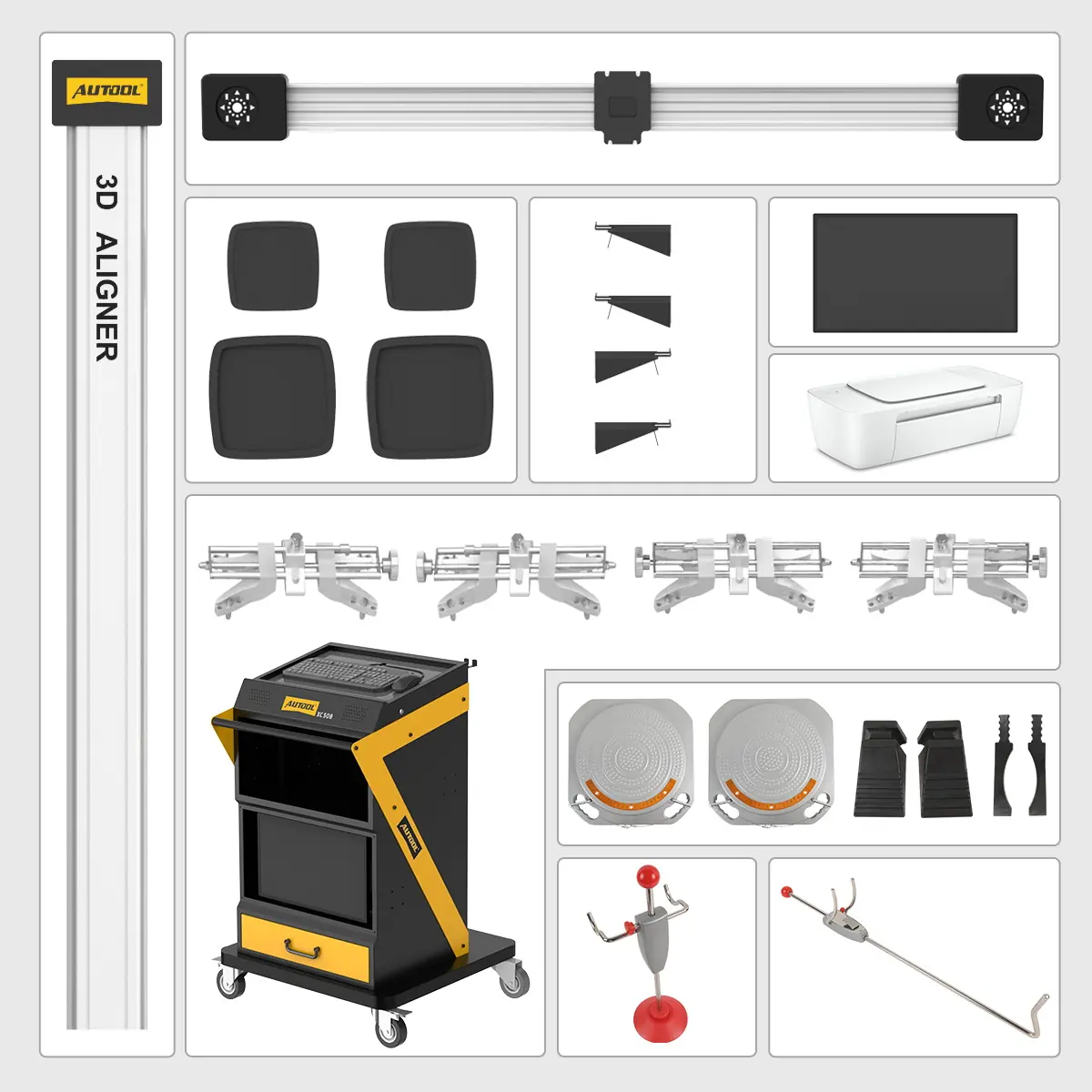
- XC508 mobile cabinet with monitor, computer, keyboard, printer and drawer areas
- Column, crossbeam and camera units
- Wheel targets, clamps and clamp hangers
- Turntables, pedals, fixtures and cables
- Bedienungsanleitung
Anwendung
- Qualify the bayConfirm lift geometry, turn and slip plates, rolling space, target sightline, power and lighting.
- Inspect and identifyCheck tires, pressures, suspension and ride height, then select the exact vehicle and specification.
- Mount clamps and targetsCenter them on clean wheel surfaces and keep every target visible to the cameras.
- CompensateRoll the vehicle to complete runout compensation.
- Measure and adjustRead the applicable angles, starting from the rear thrust reference, and make permitted adjustments.
- Remeasure and reportRepeat the measurement, check steering-wheel position and print the before-and-after report.
Installation, operation and troubleshooting: XC508 user manual (PDF)
Good to Know
Caution
- Requires a stable, level alignment bay and a qualified lift; software cannot compensate for an unsuitable surface.
- SAS, EPAS or ADAS calibration after alignment needs separate equipment.
- Choose the 110 V or 220 V version to match your local power before ordering.
Care
- Check clamp contact, target condition and mounting before every measurement.
- Follow the verification or calibration requirements after installation, moving, impact or repair.
FAQ
Does the order of adjustment matter?
Yes. Start at the rear to establish the thrust line, then move forward. Incorrect thrust affects the other readings.
How do caster, camber and toe affect tire wear?
Caster mainly affects driving feel. Incorrect camber wears the inner or outer edge slowly; incorrect toe can wear tires quickly even with only slight pulling or wandering.
How far should the aligner be from the car?
1700–2500 mm depending on the vehicle. This differs from the 1500–2800 mm camera-to-turntable distance.








 English
  German
  Spanish