
Reach Every OBD2 Pin With the Scanner Still Connected
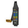
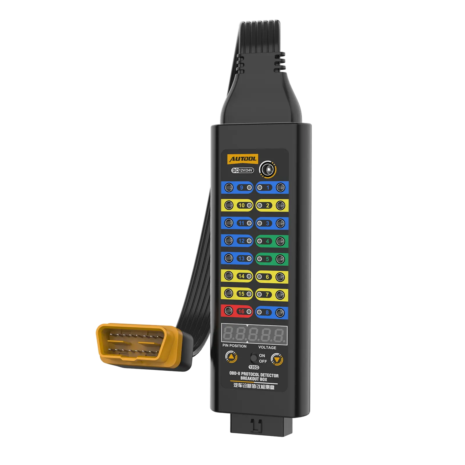
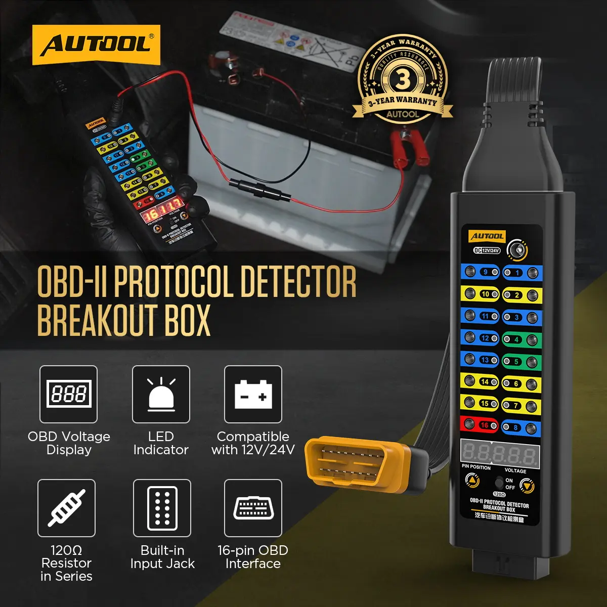
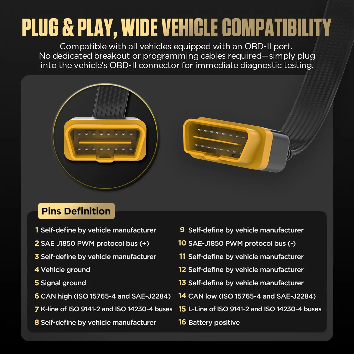
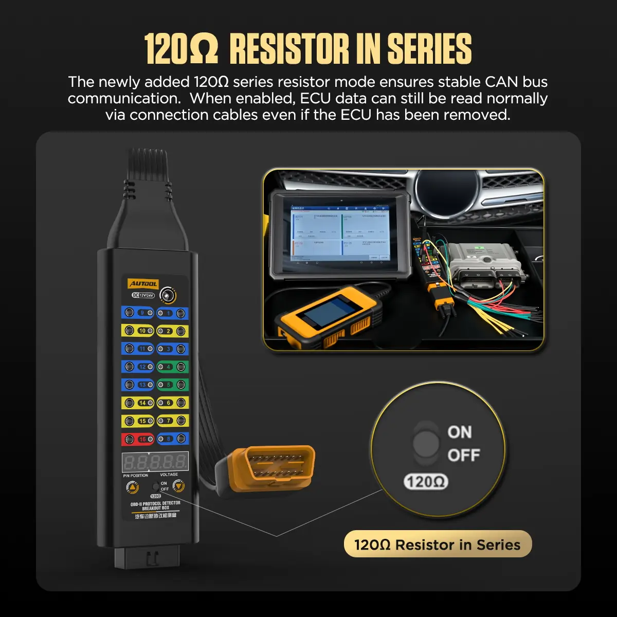
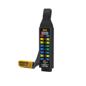
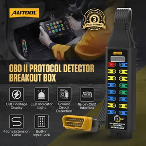
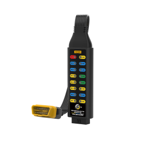
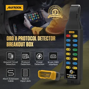
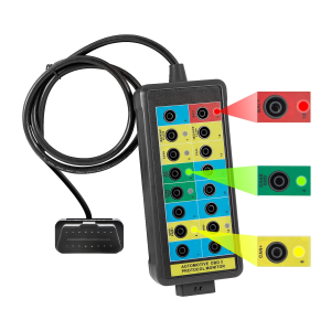
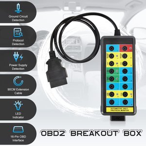
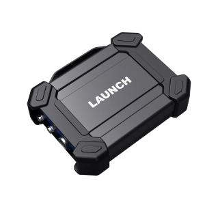
The Premium breakout box sits between the vehicle’s DLC and your scan tool, showing the selected pin’s voltage and LED status cues while all 16 pins stay open to a multimeter, oscilloscope or 4 mm leads. It adds a switchable 120 Ω series-resistor mode and an external input for temporary ECU power. It is an access tool, not a scanner.
- 16-Pin Access
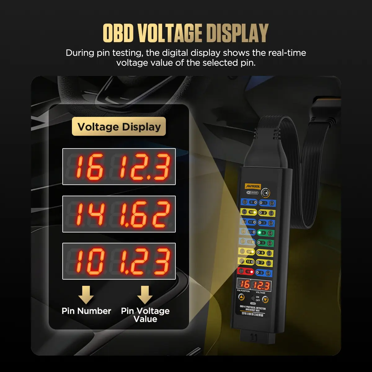
- Selected-Pin Voltage
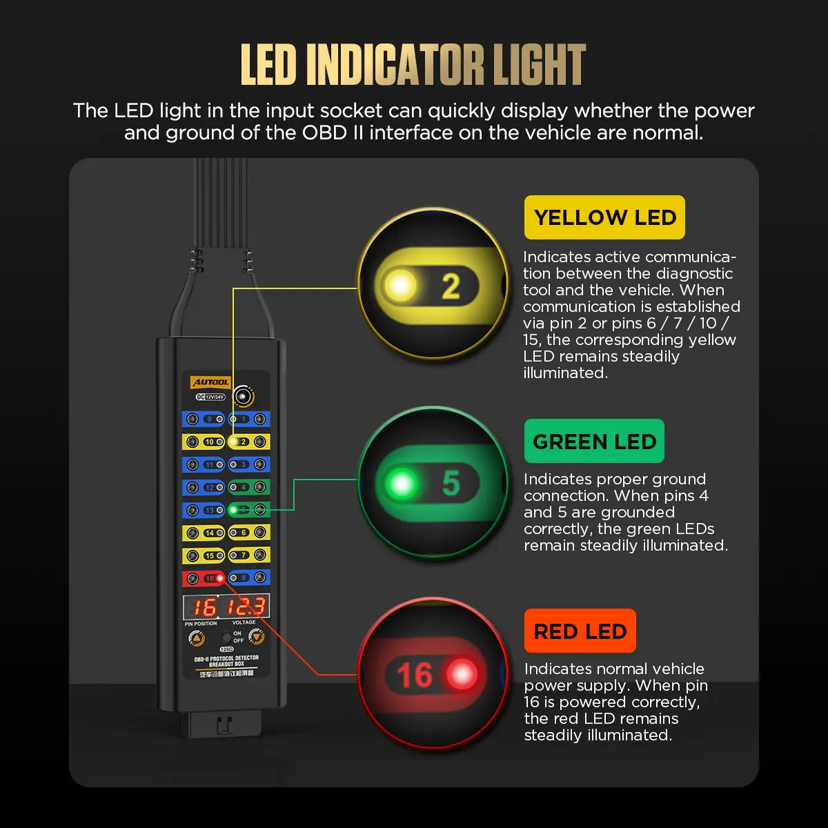
- LED Status Cues
- 120 Ω Mode
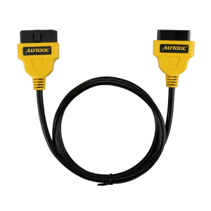
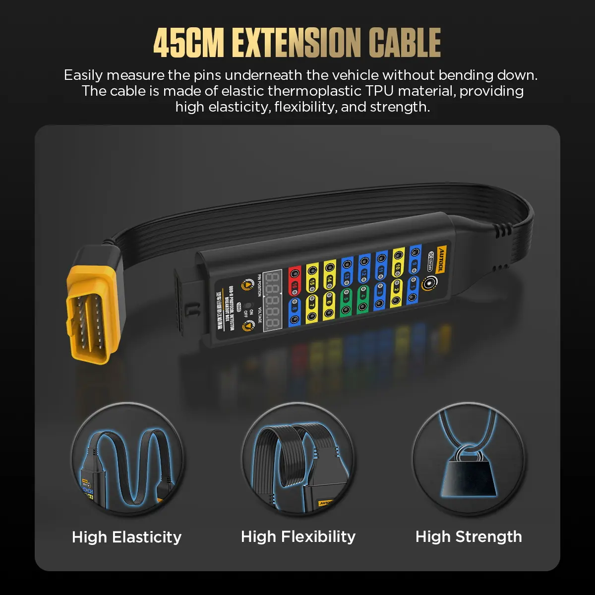
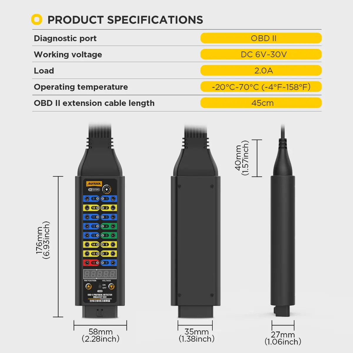
- 45 cm Cable
Key Features
-
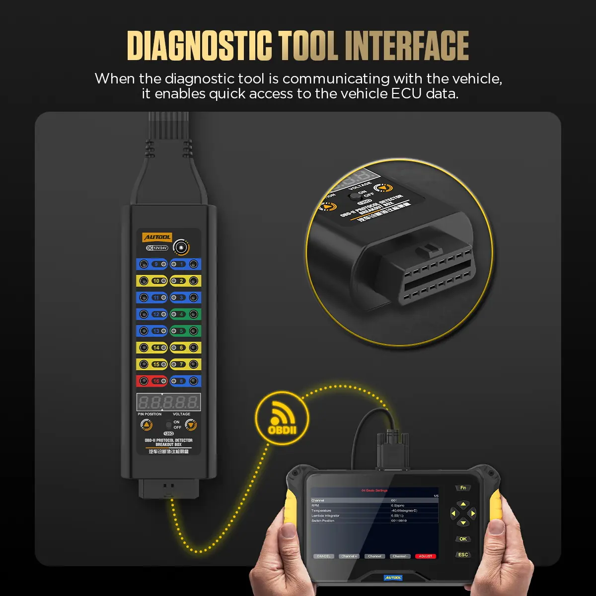
Pass-Through Scanner Connection
Keep a compatible scan tool communicating with the vehicle while you measure individual pins, without back-probing the DLC.
-
Pin Selection and Voltage Readout
The digital display identifies the selected pin and shows its live voltage; confirm against the correct reference and a suitable meter before judging the circuit.
-
LED Cues
Quick supply, ground and line-activity cues on identified OBD2 pins, to locate where to measure next.
-
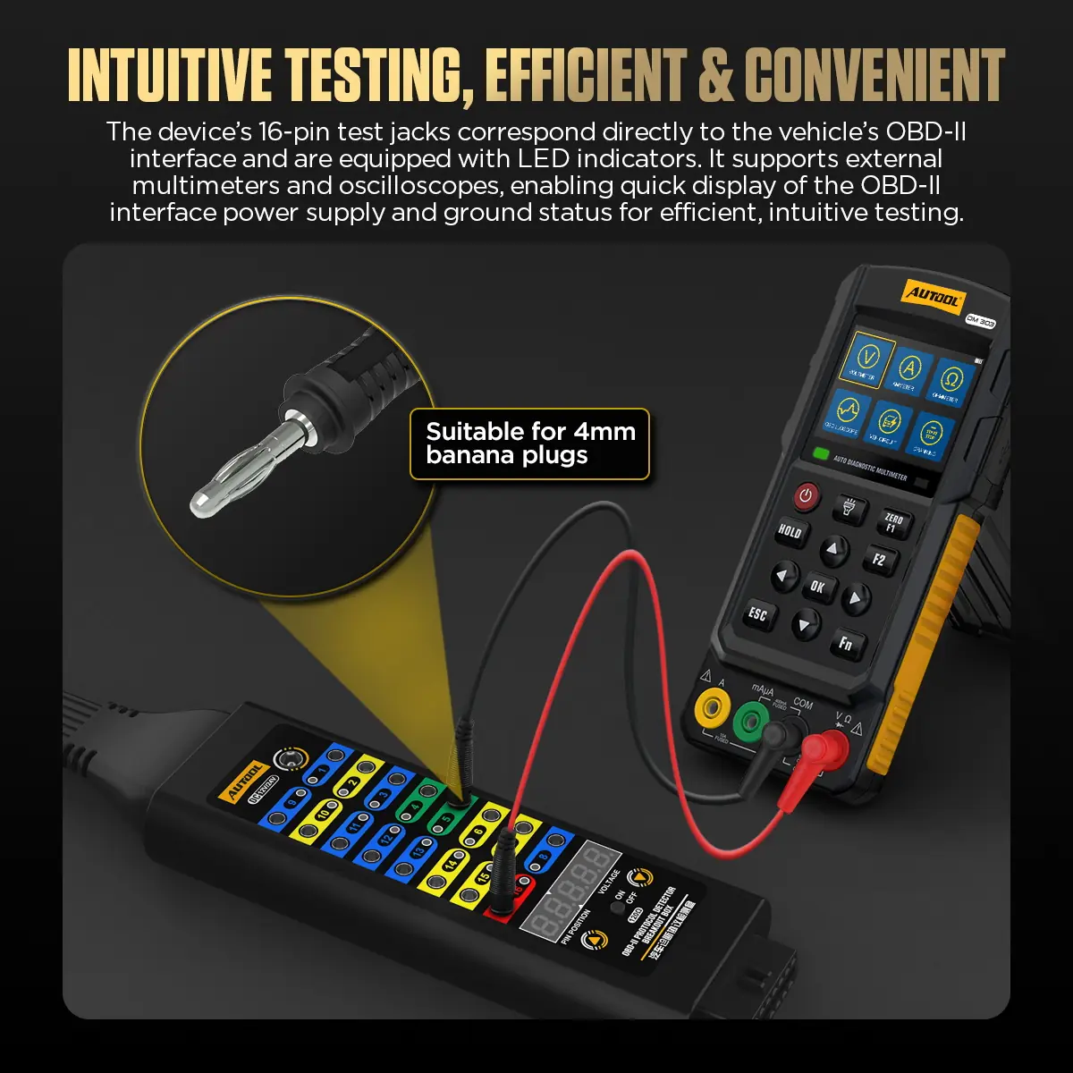
Analog Test Jacks
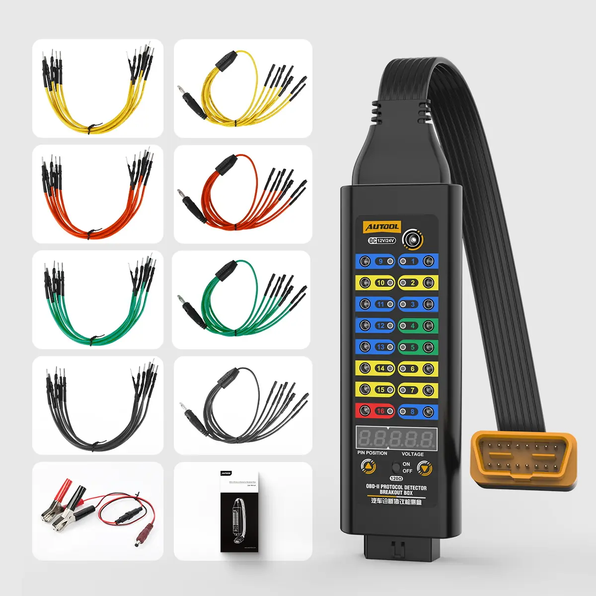
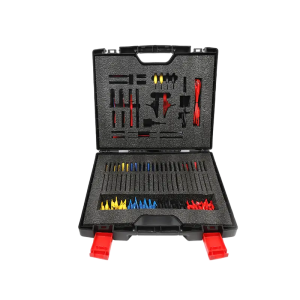
Each pin is broken out to a 4 mm jack for multimeter, oscilloscope or banana-plug lead testing of voltage, signal and communication lines.
-
Switchable 120 Ω Series Mode
For network checks where the delivered manual specifies the topology, insertion point and procedure.
-
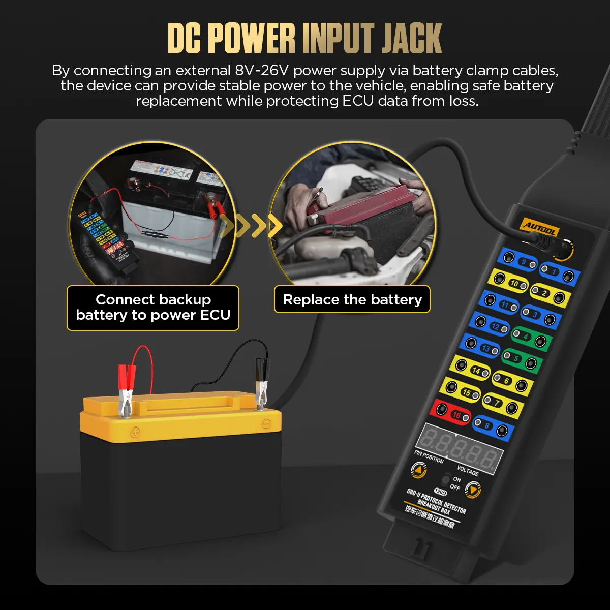
Temporary ECU Power Input
Connect a suitable external source to support ECU power during service, within the stated voltage and load limits.
-
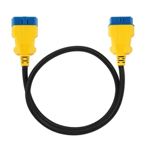
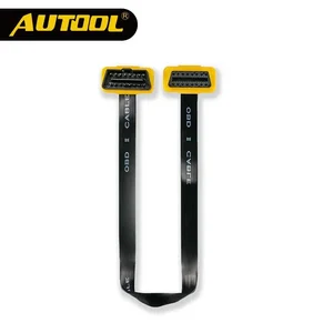
Flexible TPU Cable
The elastic, durable TPU extension makes it easier to work around the vehicle’s OBD2 port.
Model Comparison
| Basic | Upgraded | Premium | |
|---|---|---|---|
| Working voltage | DC 8–30 V | DC 8–16 V | DC 6–30 V |
| Voltage display | No | Yes | Yes |
| LED indicators | No | Yes | Yes |
| Power cable | No | Yes | Yes |
| 120 Ω series mode | No | No | Yes |
How to Use
- Identify the circuitUse the vehicle wiring diagram to identify pin functions, expected voltage, ground, network and a safe test method.
- Inspect and connectWith the vehicle in the required state, inspect the DLC and connect the box without forcing or back-feeding pins.
- Check power and groundsVerify connector supply and grounds with a suitable meter before interpreting communication activity.
- Observe and measureKeep the scanner inline when required and measure at the test jacks with a multimeter or oscilloscope.
- Record the resultNote vehicle state, pin, reference, reading or waveform, scanner result and any change when the box is removed.
Connection, display, LED cues and pin testing: Premium breakout box user manual (PDF)
Good to Know
Caution
- Do not directly short pin 16 to pin 4 or 5, and do not bridge test jacks on circuits you have not identified; incorrect jumpers, loads or back-feeding can damage vehicle networks and modules.
- External load devices must not exceed 1 A.
- The external power input does not guarantee ECU data retention or programming stability and is not a universal programming supply.
Care
- Treat the LEDs as location cues; confirm voltage, loaded ground, waveform and bus state with the vehicle diagram and a suitable instrument.
- Compare scanner communication with and without the box inline to rule out setup-induced changes.



 English
  German
  Spanish