
Reach All 16 OBD2 Pins With the Scanner Still Connected
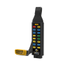
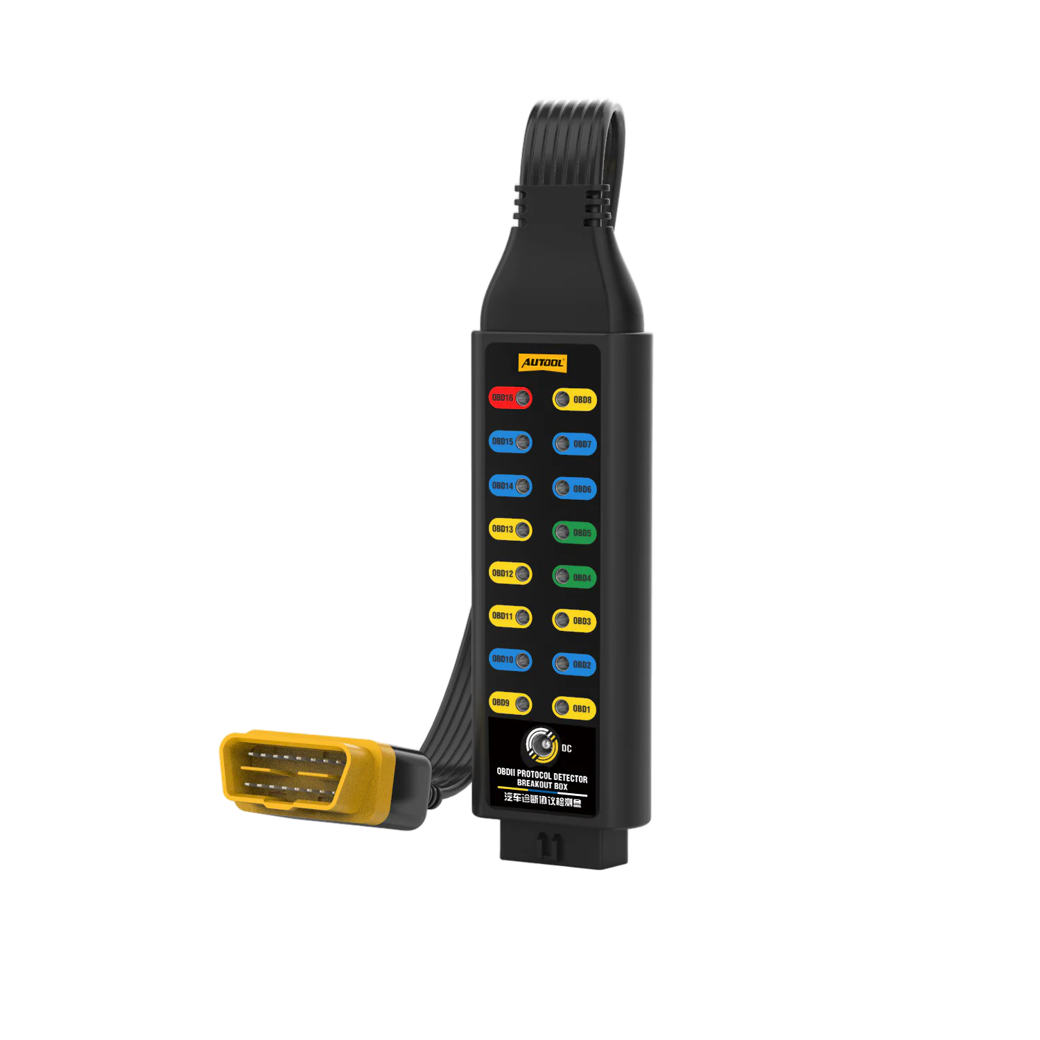
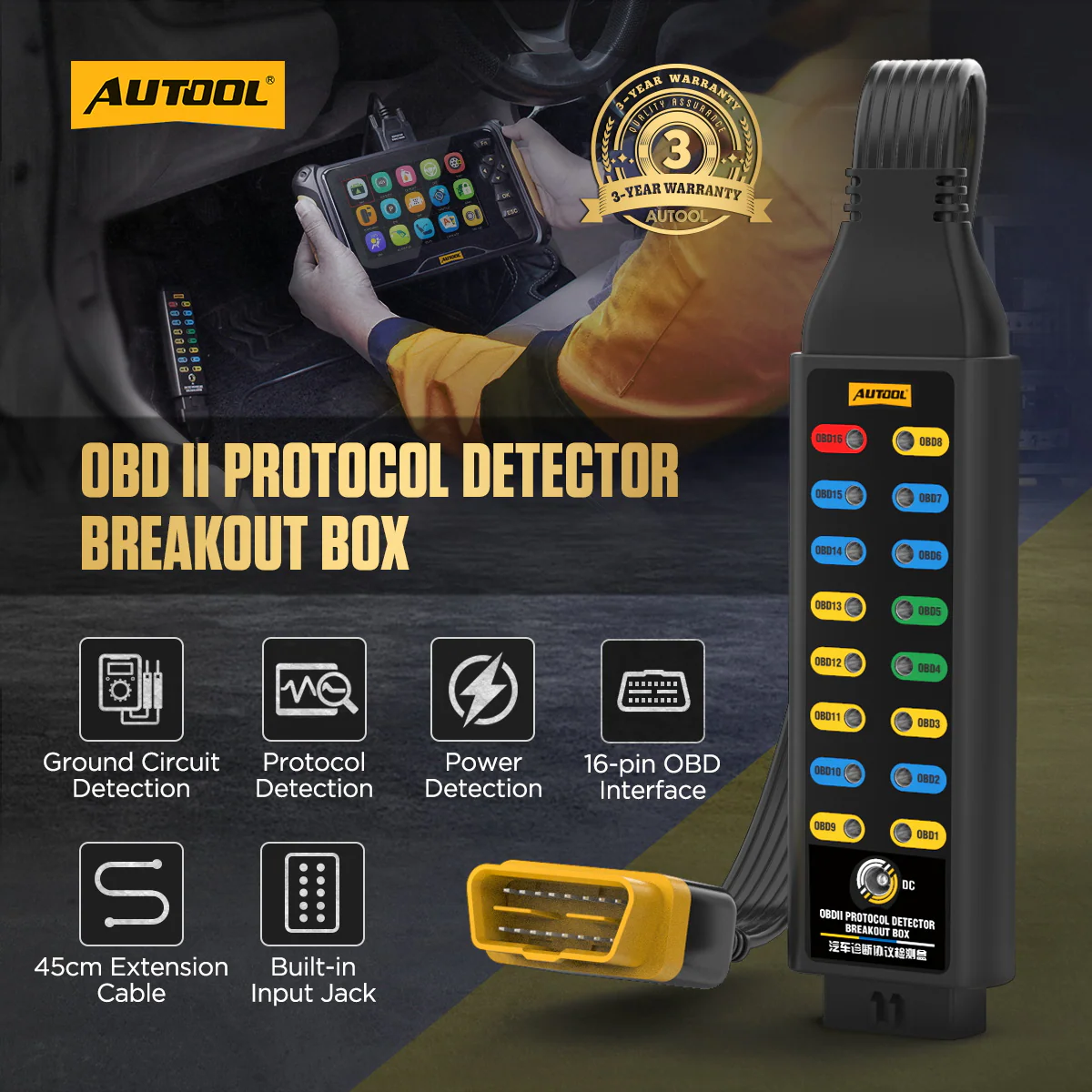
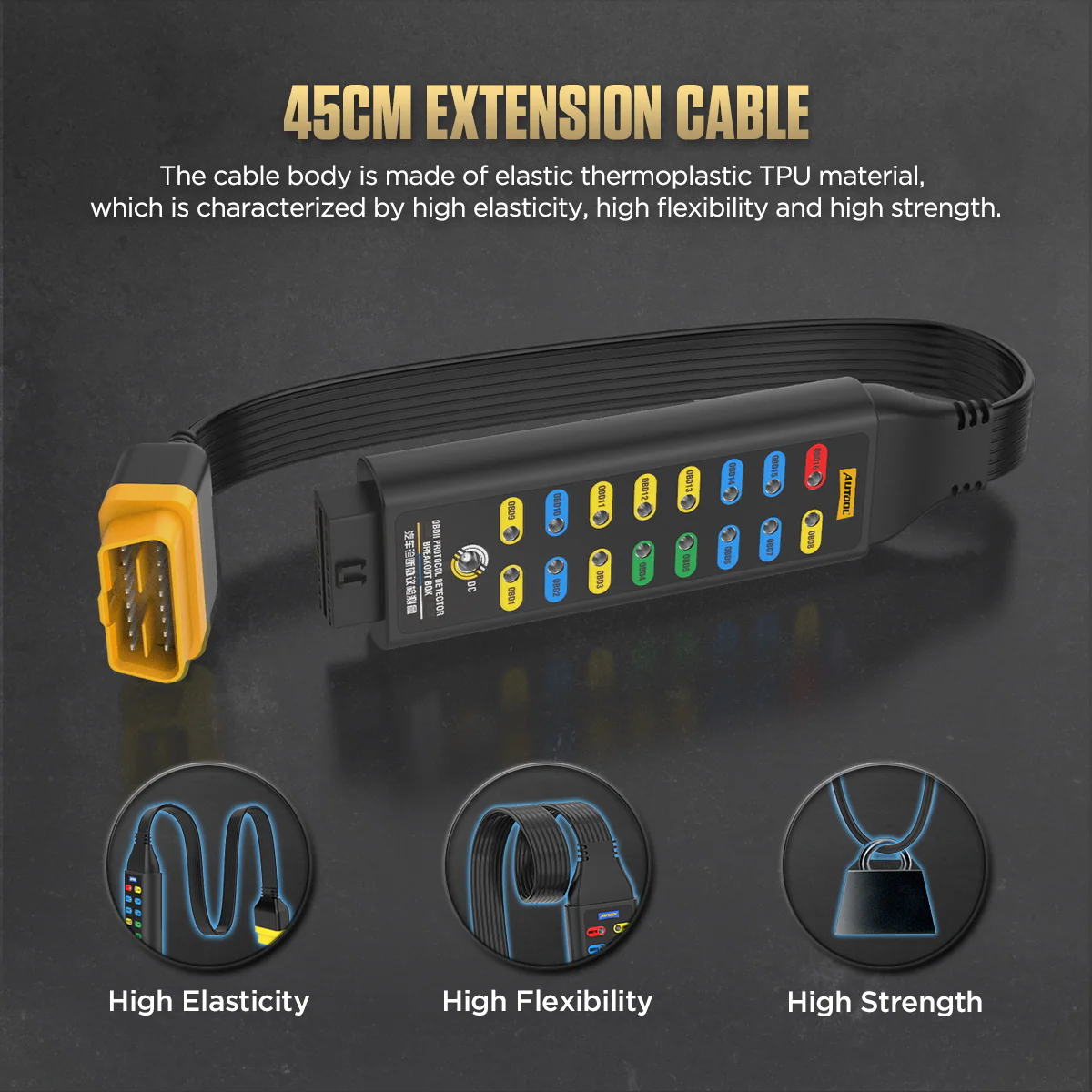
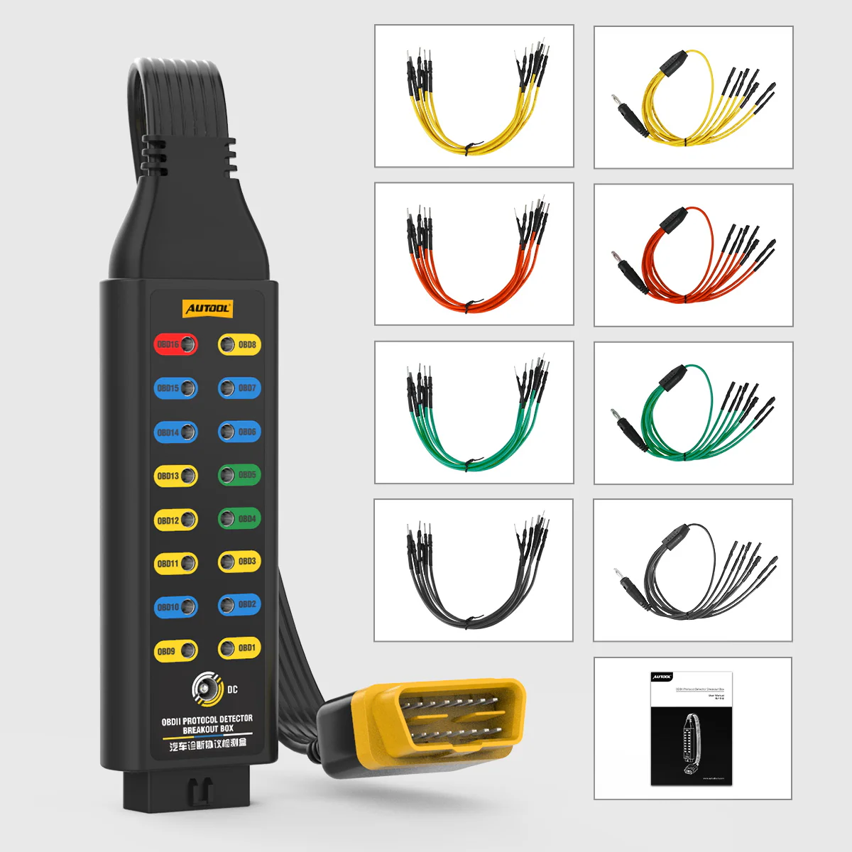
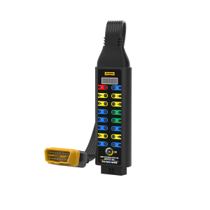
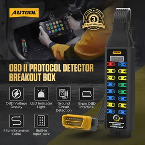
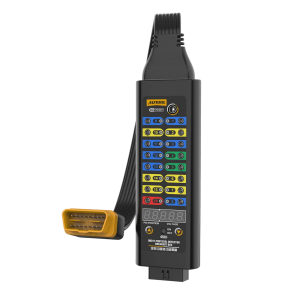
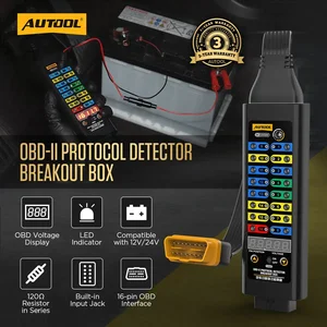
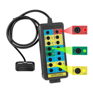
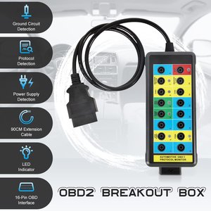
The Basic breakout box sits between the vehicle DLC and your scan tool and brings every pin out to a 4 mm test socket for a multimeter, oscilloscope or banana-plug leads. It is a passive box: there is no voltage display or LED, so all measurements are made with external instruments.
- 16-Pin Access
- Inline Scanner Pass-Through
- 4 mm Test Sockets
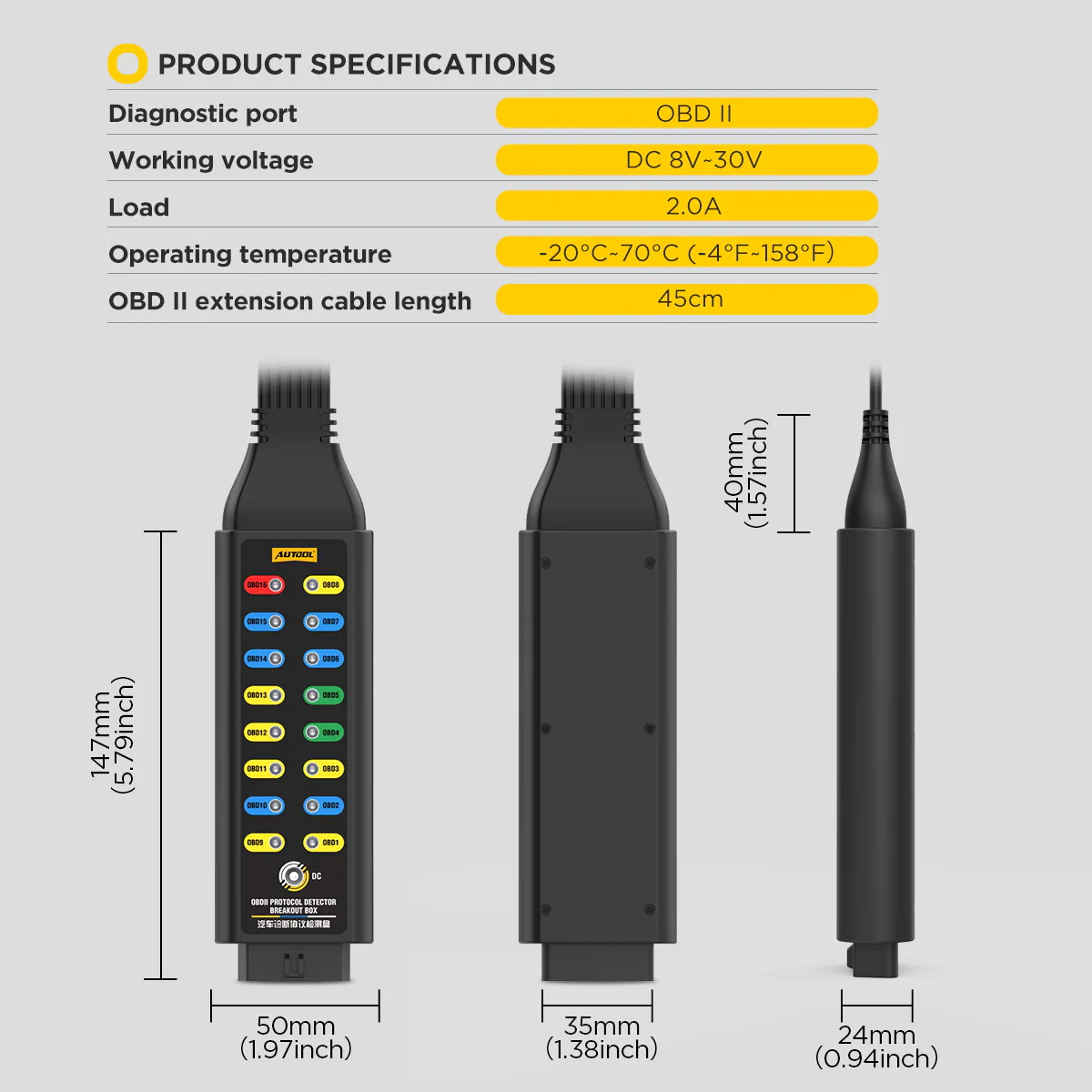
- DC 8–30 V Input
- 45 cm Cable
Key Features
-
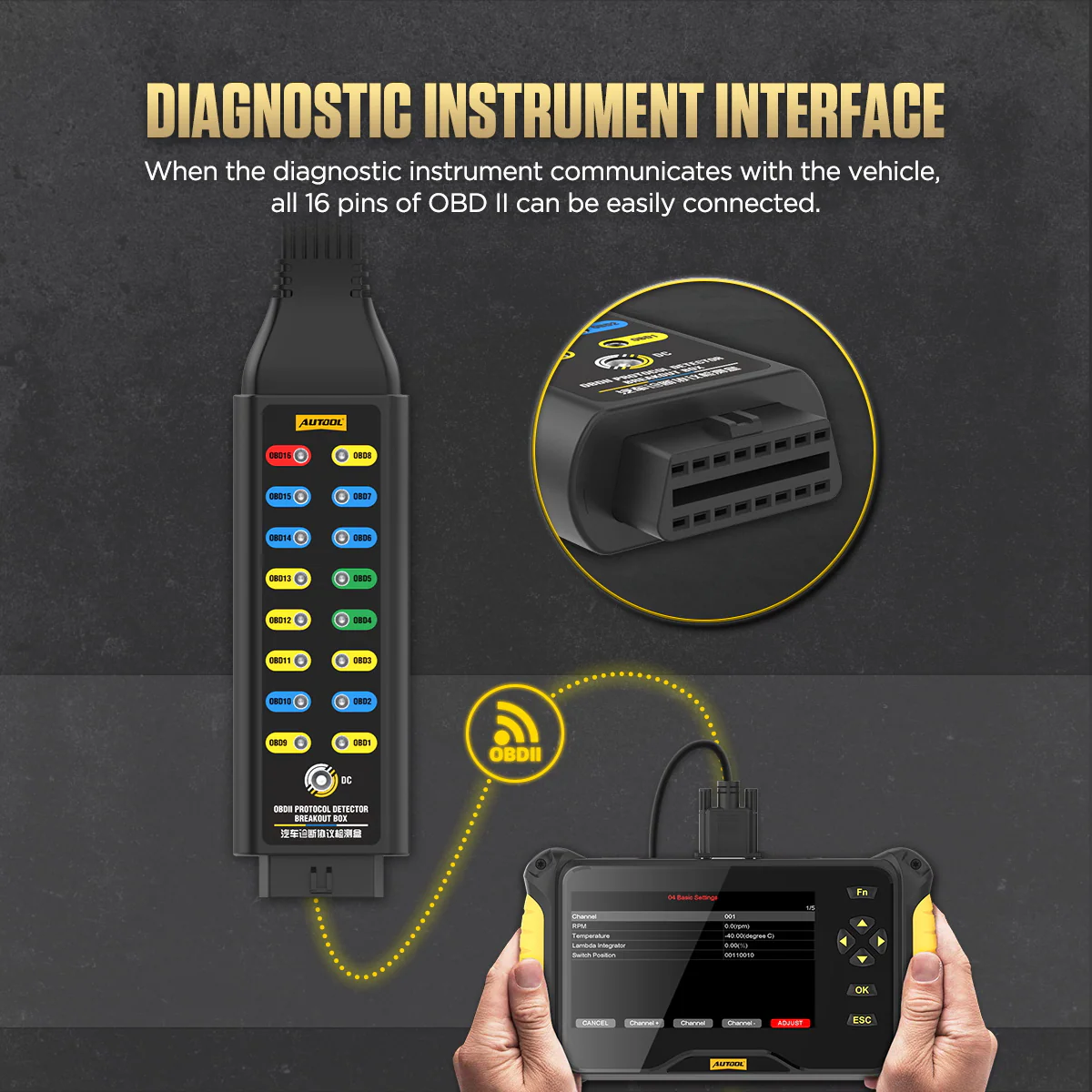
Inline Scanner Pass-Through
A compatible scan tool keeps communicating through the box while the pins stay open for testing.
-
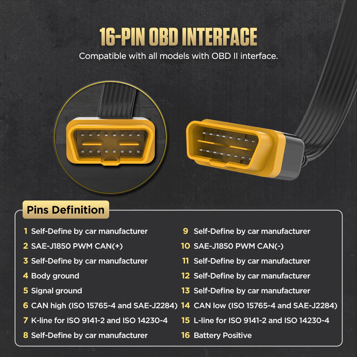
Socket Layout That Mirrors the DLC
The test sockets follow the OBD II 16-pin layout, so each signal, supply and ground pin is easy to find and probe.
-
Power, Ground and Bus Access
Check supply voltage, ground voltage drop and network activity at the identified pin with your own meter or oscilloscope.
-
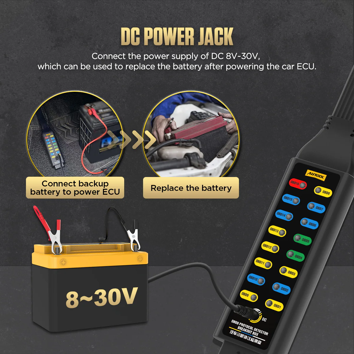
DC Input for Temporary ECU Backup
The DC jack accepts an 8–30 V supply to hold ECU power during battery replacement, when the circuit and procedure are confirmed safe.
-
Flexible TPU Extension Cable
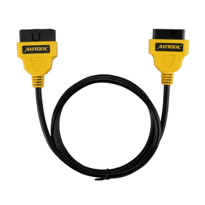
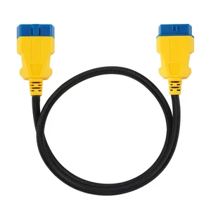
The elastic thermoplastic cable moves the test point away from the vehicle socket.
Model Comparison
| Basic | Upgraded | Premium | |
|---|---|---|---|
| Working voltage | DC 8–30 V | DC 8–16 V | DC 6–30 V |
| OBD voltage display | No | Yes | Yes |
| LED indicators | No | Yes | Yes |
| Power cable | No | Yes | Yes |
| 120 Ω series-resistor mode | No | No | Yes |
How to Use
- Identify the circuitUse the vehicle wiring diagram to confirm DLC pin functions, expected voltage, ground, network and a safe test method.
- Inspect and connectWith the vehicle in the required state, inspect the DLC and connect the box without forcing or back-feeding pins.
- Check power and groundsVerify connector supply and grounds with a suitable meter before interpreting communication activity.
- Observe and measureKeep the scanner inline when required and probe the sockets with a multimeter or oscilloscope.
- Record the resultNote vehicle state, pin, reference, voltage or waveform, the scanner result and any change when the box is removed.
Connection, pin testing and troubleshooting: OBD2 Breakout Box Basic user manual (PDF).
Good to Know
Caution
- Do not short pin 16 directly to pin 4 or 5, and do not bridge unknown sockets. Incorrect jumpers, back-feeding, loads or probe connections can damage vehicle networks and modules.
- External load devices must not exceed 1 A.
- The DC input is for confirmed backup-power procedures only; it is not a universal programming supply.
- A multimeter or oscilloscope is required for any reading and is not part of the Basic box.
Care
- Stop if the target circuit or operation is not understood.
- Compare scanner communication with and without the box inline to rule out setup-induced changes.

 English
  German
  Spanish