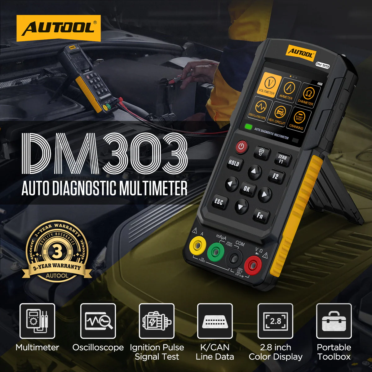

Meter, Scope and Automotive Circuit Tests in One Handheld
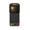
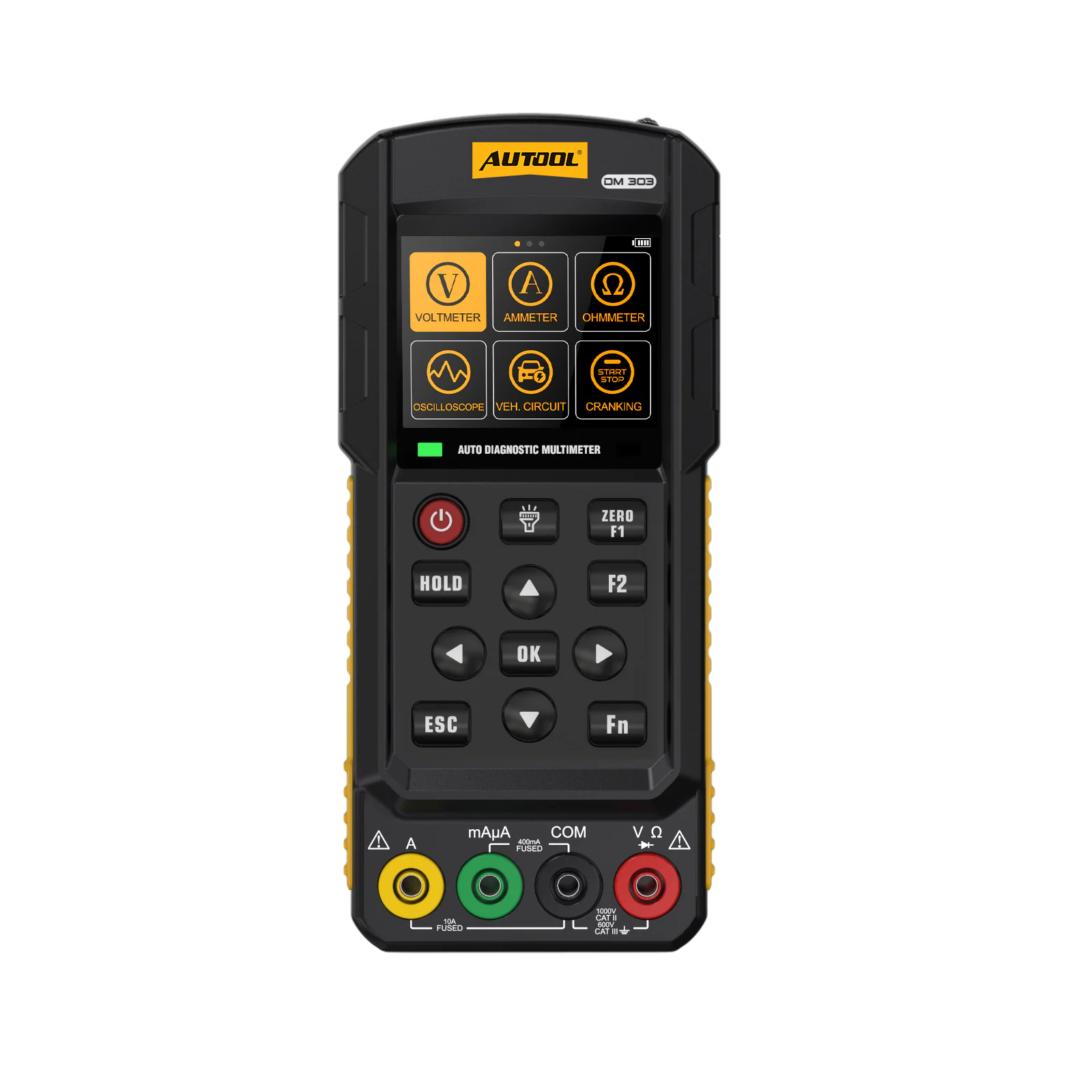
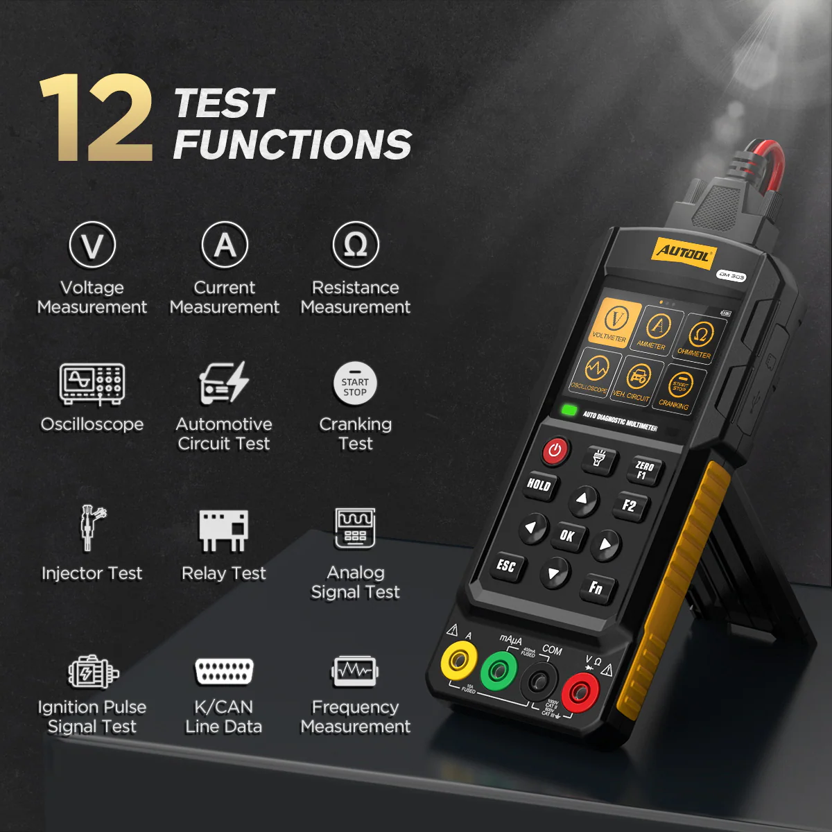
The DM303 combines a True RMS auto-ranging multimeter and oscilloscope with dedicated cranking, ignition, injector, relay, signal-output and K/CAN line modes for car, truck, bus and EV circuit work. Batteries are not included.
- DMM + Oscilloscope
- 12 Test Functions
- 5 A Drive Current
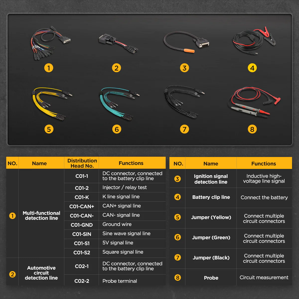
- 6 Test Lead Types
- 2.8-inch Color Screen
Key Features
-
True RMS Auto-Ranging Meter
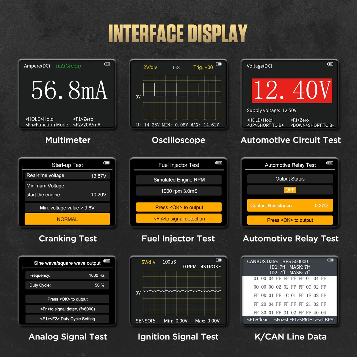
DC/AC voltage, current, resistance, diode and frequency, with auto range to cut manual range selection.
-
Cranking and Ignition Checks
Records minimum battery voltage during starting and views ignition pulse signals.
-
Injector and Relay Testing
Drives supported electromagnetic injectors, including supported GDI injectors, and reads real-time injector signals; also tests relays.
-
Signal Output
5 V square, 5 Vpp sine and 12 V square outputs for signal simulation on a documented, permitted load.
-
K/CAN and K/LIN Line Data
Views bus line data for circuit-level diagnosis.
-
Kit in a Toolbox
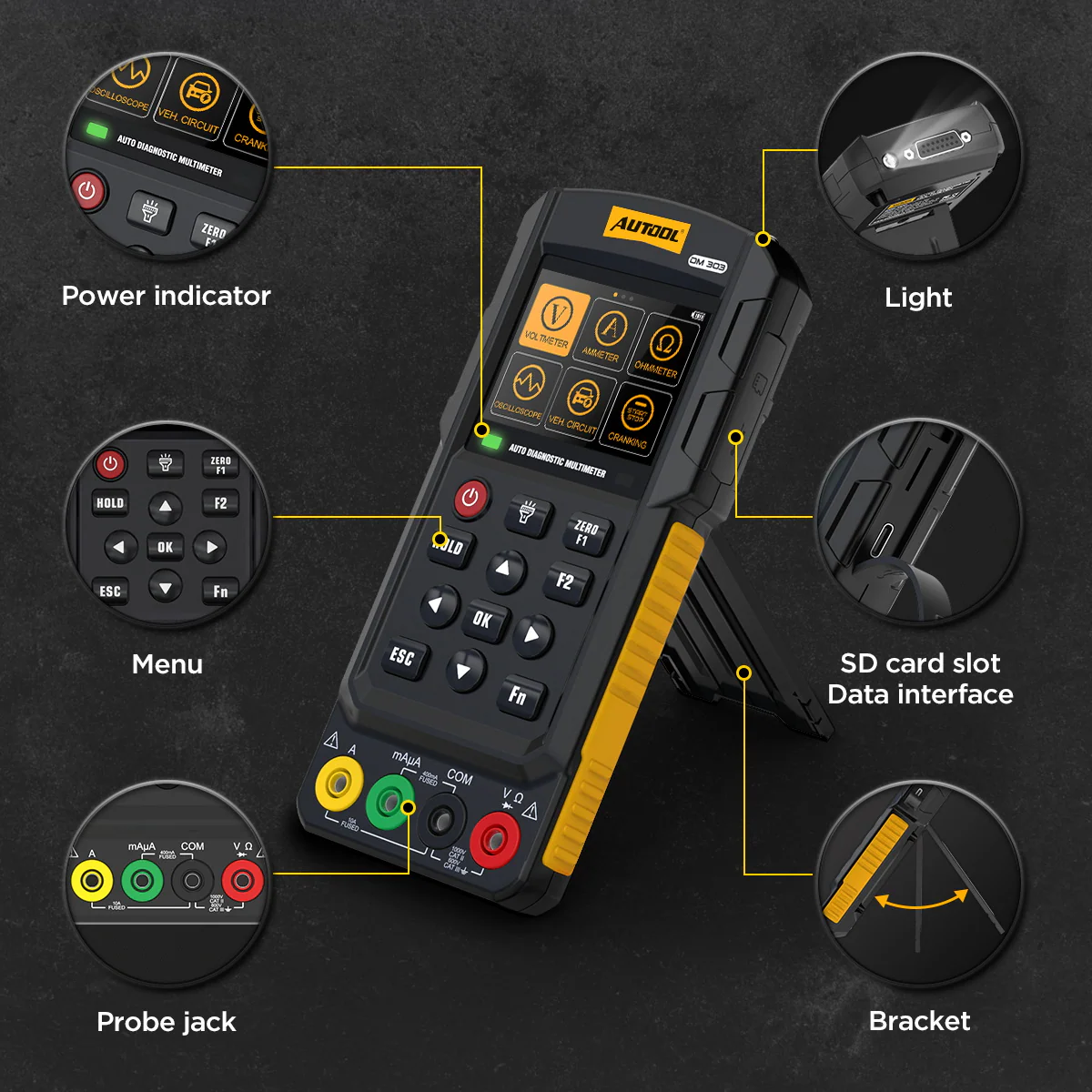
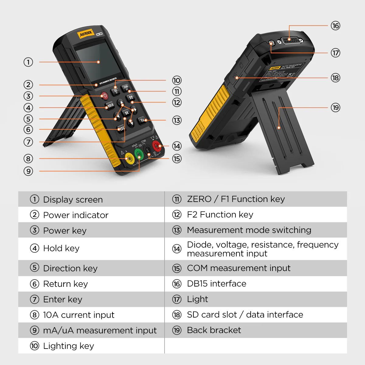
Rear stand for upright viewing, built-in flashlight, and a toolbox that holds the meter and leads together.
More Specifications
| Injector drive signal | 500–6000 rpm |
|---|---|
| Data hold | Data lock and clear |
| Interface languages | Including English, French, Portuguese, Polish, Spanish, Japanese, Russian, Italian, German, Dutch, Korean and Chinese |
| Optional lithium battery | 503450 3.7 V 1000 mAh style shown in the reference image; confirm connector and size before fitting |
DM303 vs DM301
| DM303 | DM301 | |
|---|---|---|
| Funciones | 12 | 6 |
| Test lead types | 6 | 2 |
| Circuit drive current | 5 A output / 5 A input | No |
| Injector drive signal | 500–6000 rpm | No |
| Added test modes | Injector, relay, circuit, cranking, signal simulation, CAN and K/LIN line data | Voltage, current, resistance, frequency, oscilloscope, ignition pulse only |
What’s in the Box
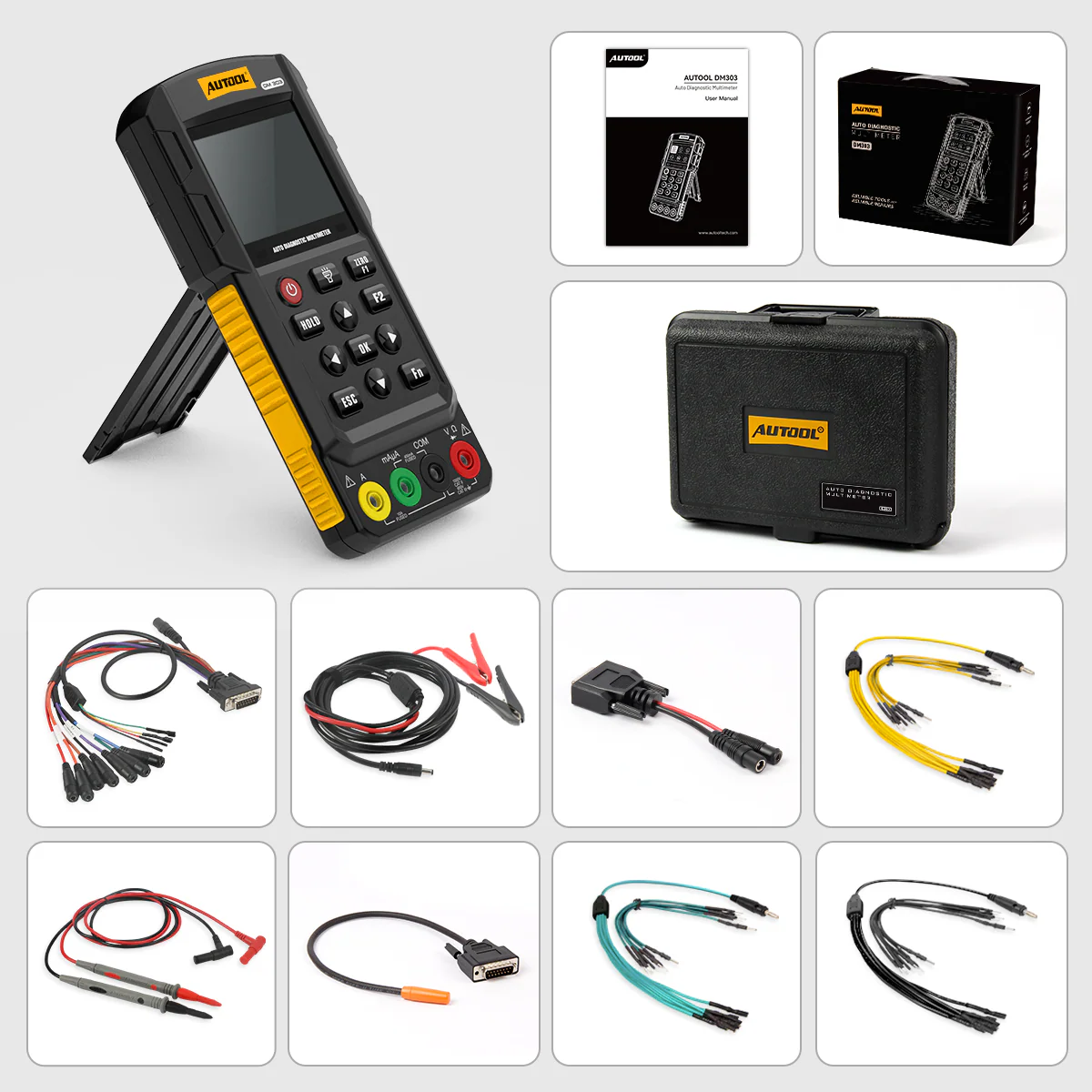
- DM303 automotive diagnostic multimeter
- Portable toolbox
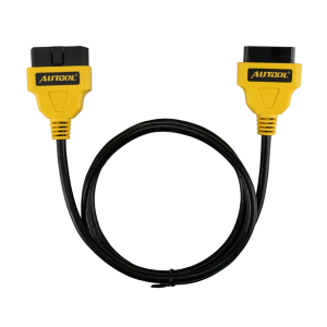
- Multifunction test lead
- Battery clip cable
- Multimeter probes
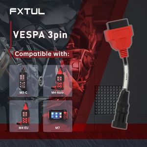
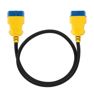
- Jumper and adapter cables
- Additional test leads
- User manual
How to Use
- Define the measurementUse the wiring diagram to identify the expected signal, reference point and safe mode.
- Inspect leads and ratingsConfirm the terminal, fuse, lead and probe ratings for the task.
- Select the modeChoose the function and start on a safe range.
- Qualify any active outputBefore injector, relay or signal output, confirm component type, pinout, supply, current and permitted mode.
- Probe the circuitConnect to the correct reference and test point without bridging terminals.
- Record and verifyNote the value, compare it with the vehicle specification and recheck before naming a root cause.
Modes, ranges and safety: DM303 user manual (PDF).
Good to Know
Caution
- Batteries are not included. Use 4 × 1.5 V dry batteries or a compatible lithium battery, purchased separately.
- Never charge dry batteries in the device; only a compatible rechargeable lithium battery may be charged.
- Keep injector drive and signal outputs off ECU outputs, SRS circuits, powered data lines and unknown modules.
- 120 V injectors are not supported.
FAQ
What does the cranking test result mean?
The DM303 records minimum battery voltage during starting and uses 9.6 V as a general reference. A lower reading can point to a weak or aging battery or a starting-system issue; apply the battery or vehicle maker’s procedure.
Can it replace a full vehicle diagnostic scanner?
No. K/CAN line data helps with circuit-level diagnosis, but it is not a full vehicle scan.
Does a drive response prove an injector is good?
No. It does not by itself prove spray pattern, flow or root cause.



 English
  German
  Spanish